In an earlier post I demonstrated how to go about testing for coolant leaks. I initially detected a cracked hose but even after temporarily sealing it with JB Weld and conducting the pressure test again, the system still leaked at the same spot. After discussing with 986forum members, I decided to try changing the water pump, thermostat, replacing the main hoses near the engine and change the serpentine belt anyway. This would remove all the issues and would make the system as good as new. This post describes the water pump and thermostat replacement process.
Replacement Parts Needed
I ordered all these parts from PelicanParts.com and they have a Water Pump replacement kit (Pelican part number PEL-WPBK986-01N) which holds most of these items, but you may choose to buy the parts from a dealer or elsewhere. So here are the part numbers for everything for a 2001 Boxster S. I also purchased genuine Porsche or OEM grade parts, because they are just better manufactured and in the long run are cheaper to operate.
To get a list of all the part numbers for the 986 Porsche refer to the catalog in this post.
- Water Hose to Water Flange at Oil Pump Housing (Large Hose) Part#
996-106-501-07-M253 - Water Hose - Thermostat housing to water pipe Part#
996-106-502-06-M253 - Coolant Drain Plug on Oil Pump Housing (10 x 1mm) Part#
900-219-007-01-OEM - Aluminum Washer (10 x 14 x 1mm) Part#
900-123-144-30-OEM- 2 Units - Rubber O-Ring 15x2.5 Part#
999-707-387-40-OEM - Thermostat with Cover and Gasket Part#
996-106-013-61-M2 - Water pump Gasket Part#
996-106-340-54-OEM - Water pump bolt (6 x 30mm) Part#
900-378-177-01-M100- 2 Units. This is the longer bolt. - Water pump bolt (6 x 25mm) Part#
900-378-013-01-M100- 5 Units. These are the shorter bolts. - A/C Poly-Rib-belt 6Kx2115 Part#
996-102-151-66-OEM- the serpentine belt. - Water pump Part#
996-106-011-57-M100 - Coolant / Antifreeze Original Porsche Pink G40 (2-3 gallons) Part#
000-043-305-75-M100or Aftermarket Pink G40 - Distilled water (2-3 gallons)
- Hose clamps - 4-5 Units. These will need to be replaced when you open them up.
- Blue Threadlocker - medium strength threadlocker for water pump bolts.
- Optional hose: Part#
996-106-212-12 - Optional coolant expansion tank cap which is part#
996-106-447-04
You also needs tools like a 7mm socket, a T5 torx screw socket or screw driver, various socket wrench extensions for opening bolts in difficult to reach spots and a magnetic bowl to store the bolts that you remove. You will also need a metal pick and hose clamps to remove hoses (Figure 8).
For the water pump it is recommended to use new bolts and for the thermostat you can get away with reusing the old bolts.
You will also need a bucket to hold the leaking coolant and potentially another to mix the replacement coolant in.
Optionally, you could buy a tool like a Coolant Vacuum Refill Kit to refill the coolant correctly in the car. This kit also has a coolant/radiator pressure testing kit in it, so maybe a good combined purchase for the price.
Remove the Rear Splash Shield
In an earlier post on oil change, we described how to jack up the car safely.
But the Bentley manual suggests another way to lift the full rear of the car is to get the jack between these two bolts as shown in Figure 1. Remember to use 3-ton jack stands.
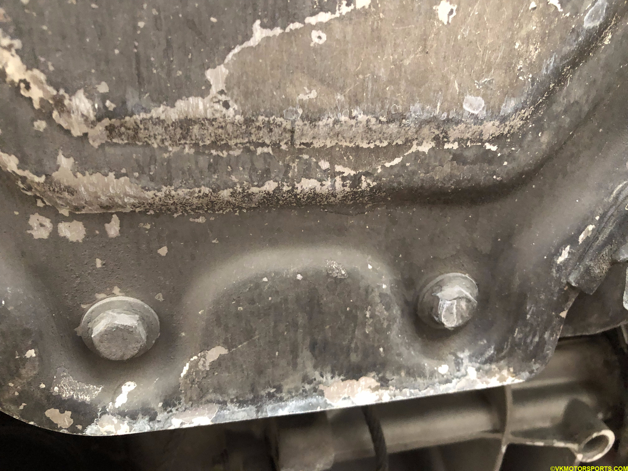 Figure 1. Jacking point is between these two bolts
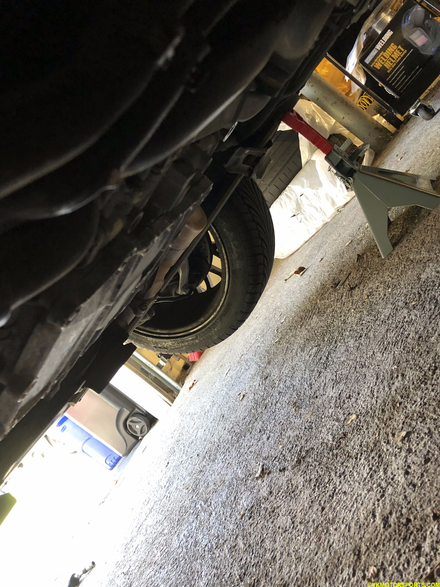 Figure 2. Jack up the car with jack stands
Now that the car is jacked up, start removing the rear splash shield (Figure 3a) for the engine. There are 6-7 nuts (Figures 3b and 3c) that need to be removed with a 10mm socket. Make sure you save these nuts in a container or ziploc bag. If you are using a QuickJack or a mid-rise lift, some of these nuts may not always be accessible, so you may want to remove them first before using a mid-rise lift. Once all the nuts have been taken out carefully pull the splash shield (Figure 3a) towards you and keep it aside (Figure 4). You may want to wash the splash shield with soap and water if it is dirty.
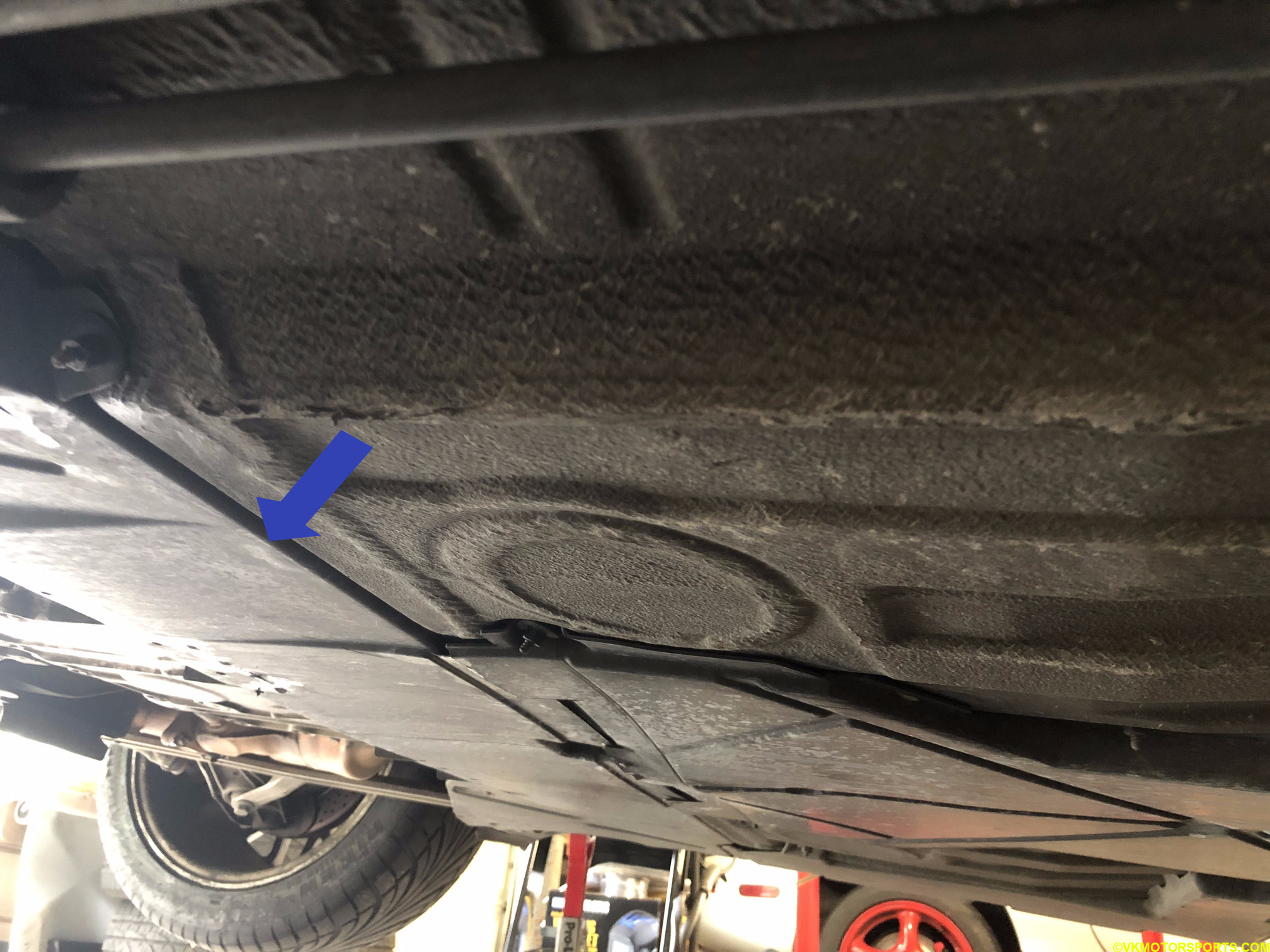 Figure 3a. Remove splash shield
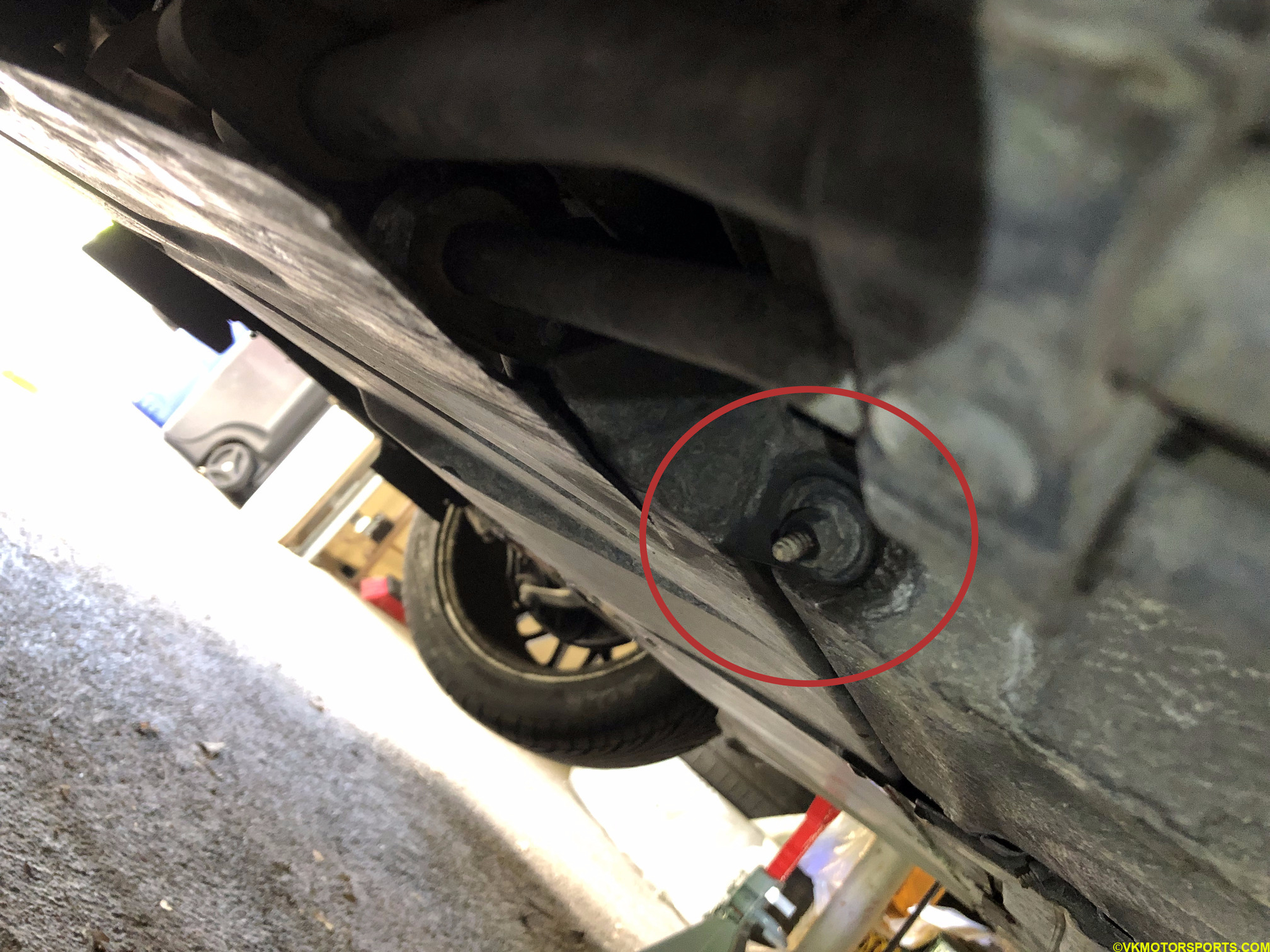 Figure 3b. Splash shield nut on the right rear corner of the car
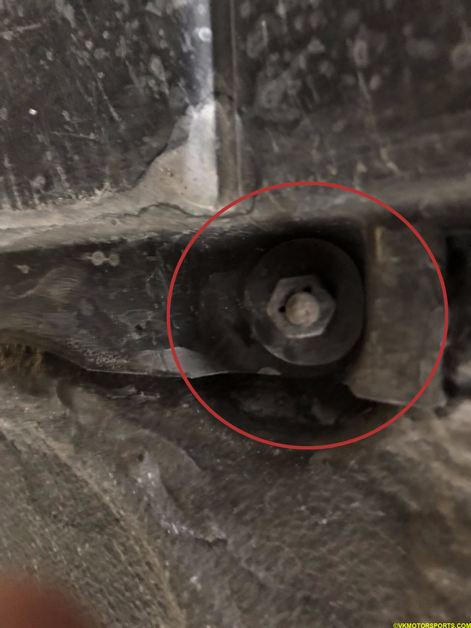 Figure 3c. Splash shield nut in the middle of the car
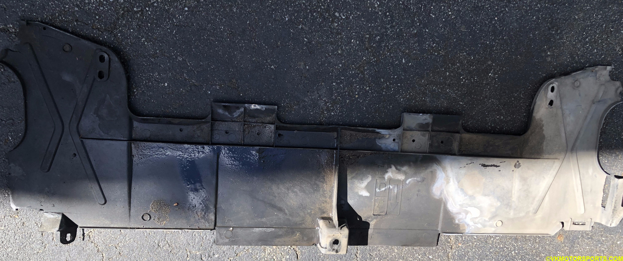 Figure 4. Splash shield has been removed
Drain the Coolant
Place a 5 gallon container below the drain plug (Figure 5) so that it can catch draining coolant.
Using a T5 socket (Figure 6) open the drain plug (Figure 5) and start draining the coolant from the engine as shown in Figure 7.
The coolant will drain for about 30 minutes before it stops. Using a new coolant drain plug part# 900-219-007-01-OEM and a new aluminum washer part# 900-123-144-30-OEM close the drain plug and hand tighten it or torque it between 7-11 ft-lbs.
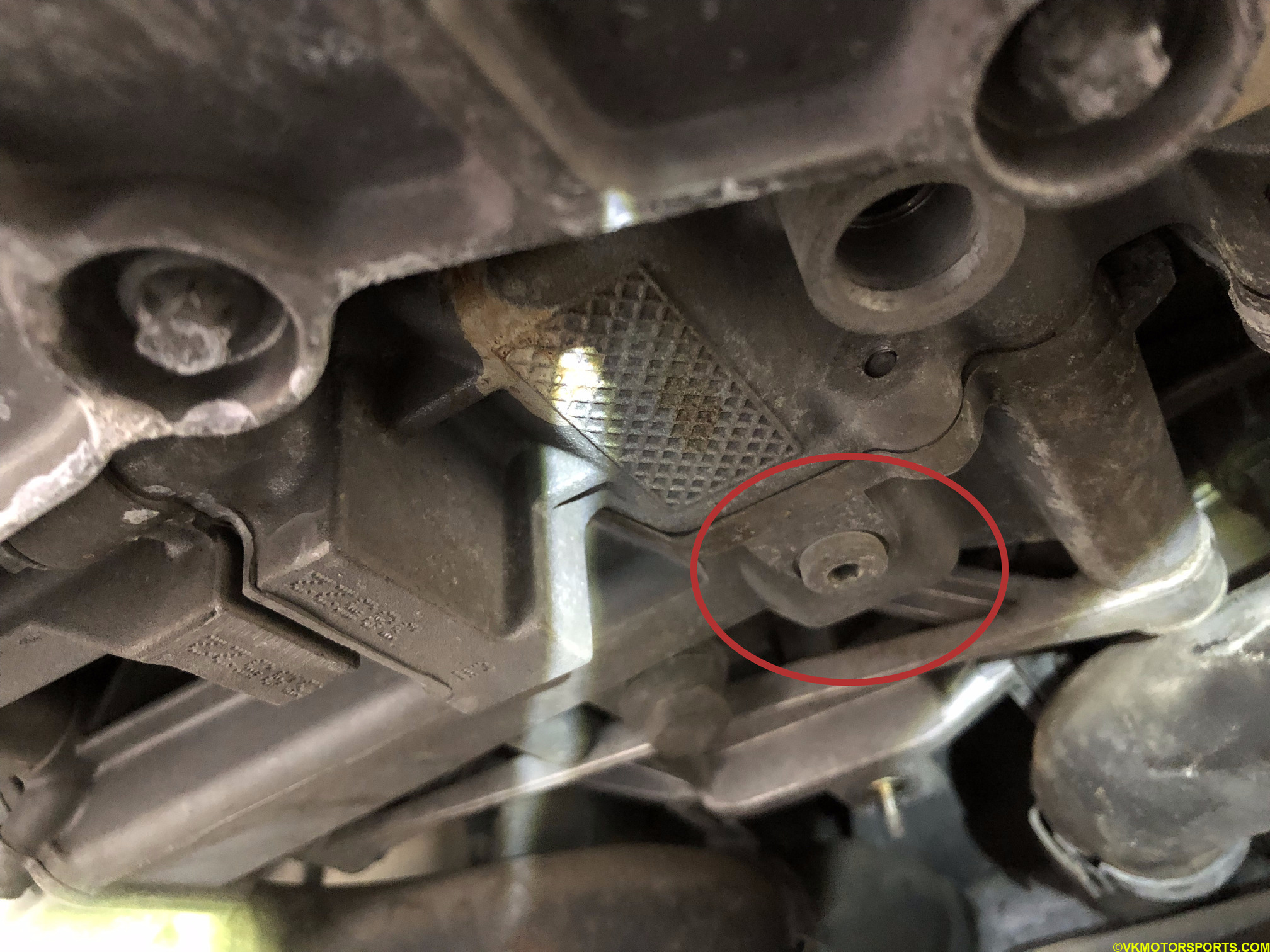 Figure 5. Coolant drain plug
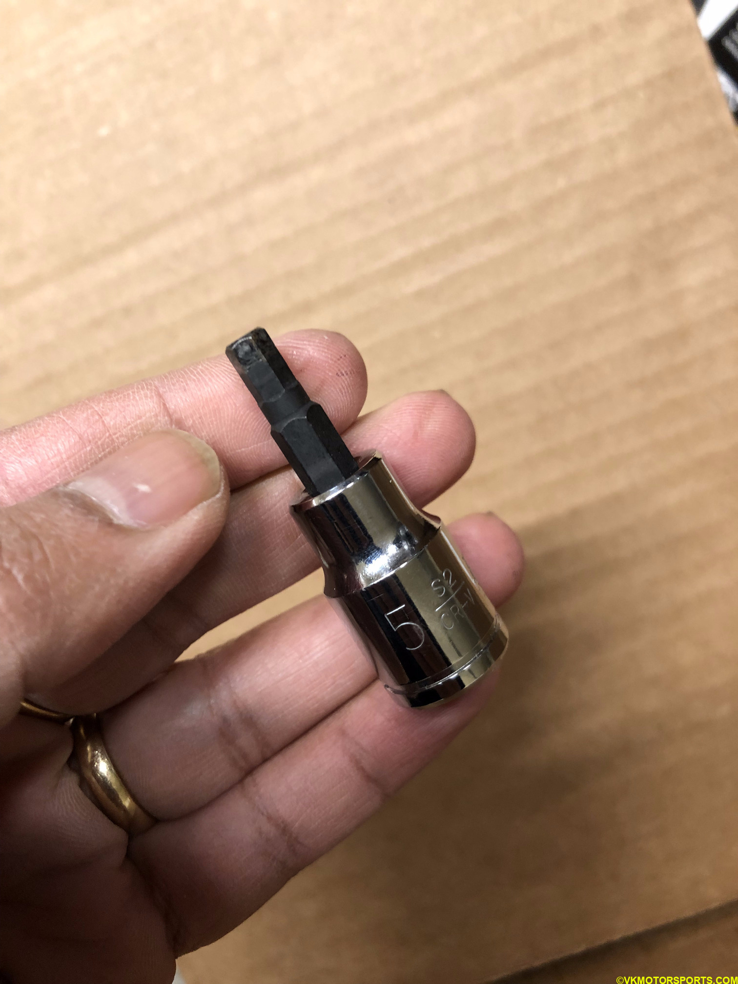 Figure 6. T5 socket
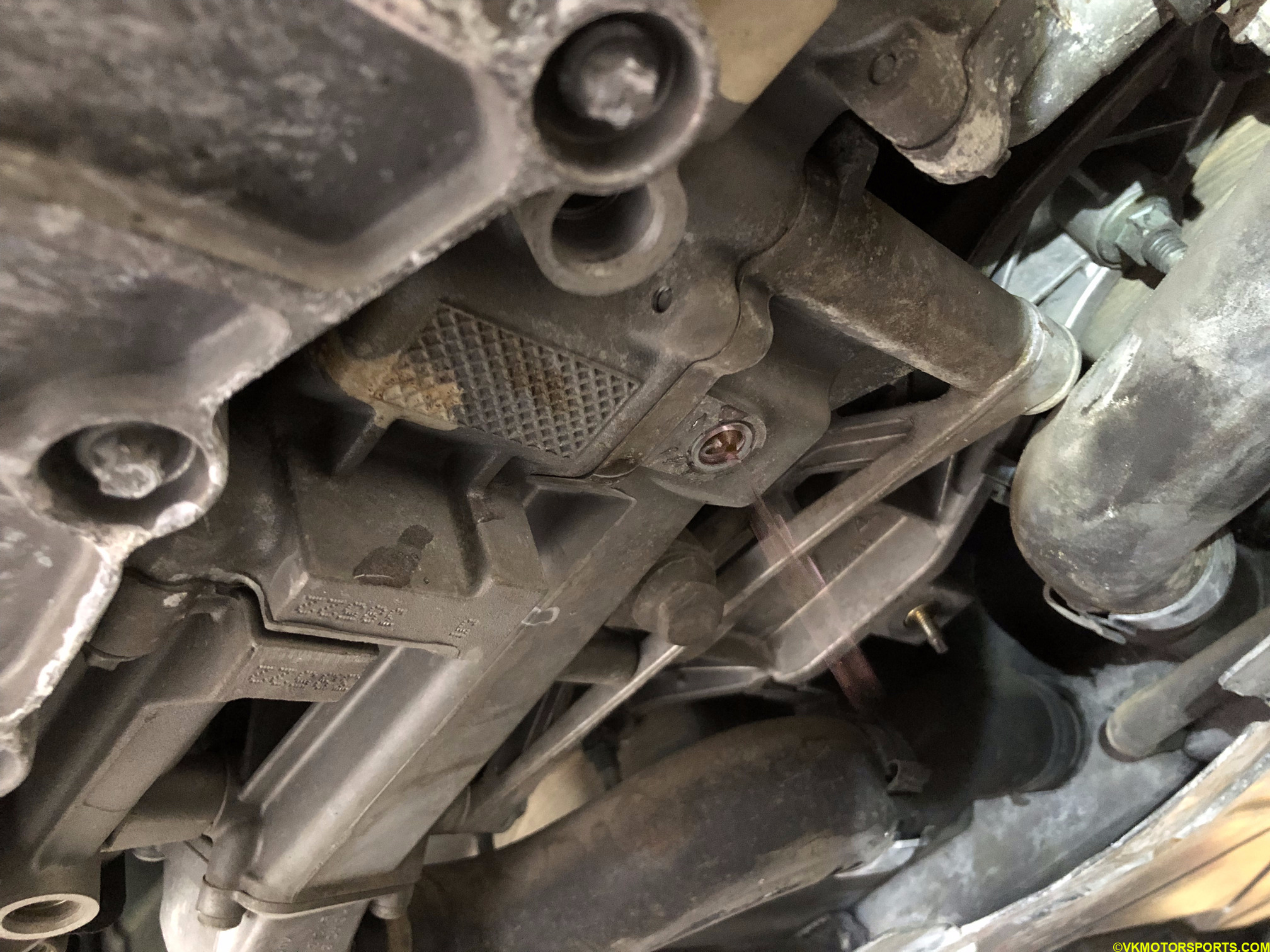 Figure 7. Coolant is draining
Using a 7mm socket (Figure 8a) loosen the hose clamps of the large hoses connecting the thermostat and water pump, respectively, as shown in Figure 8b. You may have to slide them off the hose
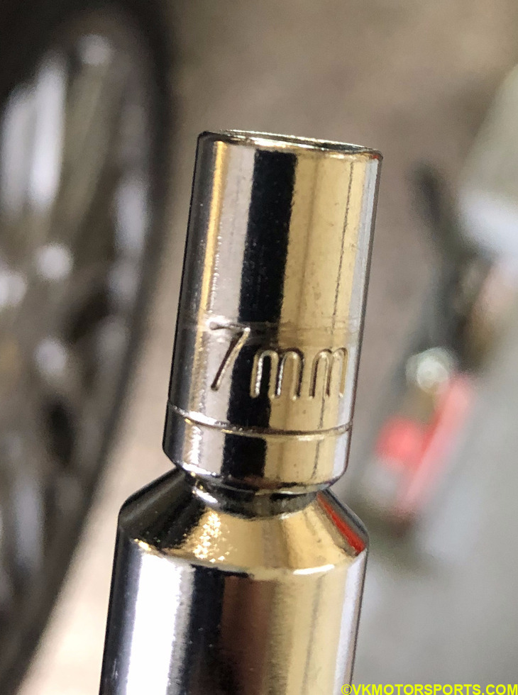 Figure 8a. 7mm socket
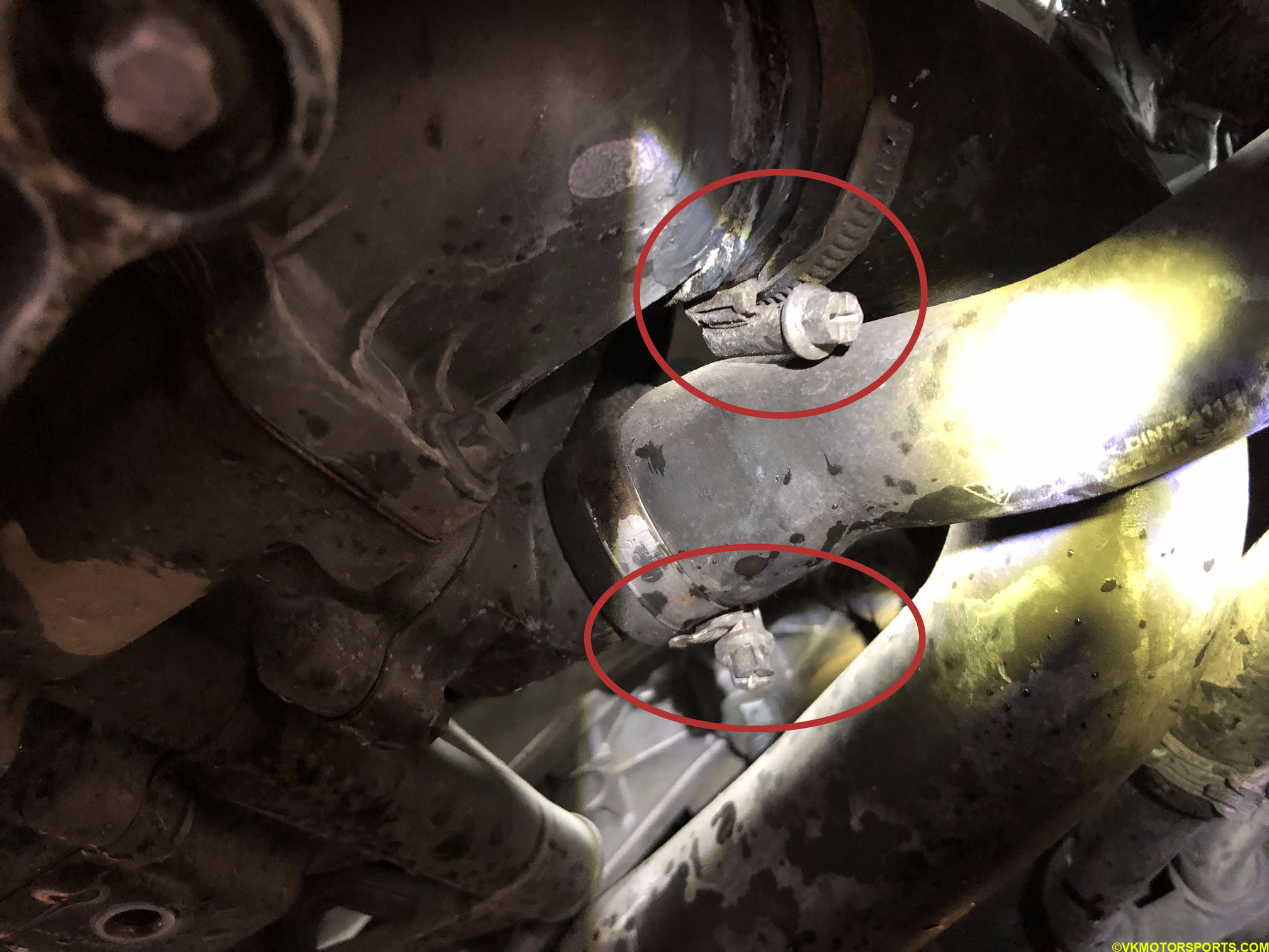 Figure 8b. Remove the circled hose clamps
If the hose clamps are worn out, which in my case they were, you must replace them. If they do not come out, you can cut them out.
Removing the large hoses connected to the thermostat and water pump can be quite difficult. It may take about 5-10 minutes per hose since they are stuck on there for several years in many cases.
I used the tools in Figure 9 to remove the hoses. The pick was used to lift the hose end up away from the metal it was stuck to, and the channel locks with duct tape around them were used to pull the hose out of the connection with the metallic parts.
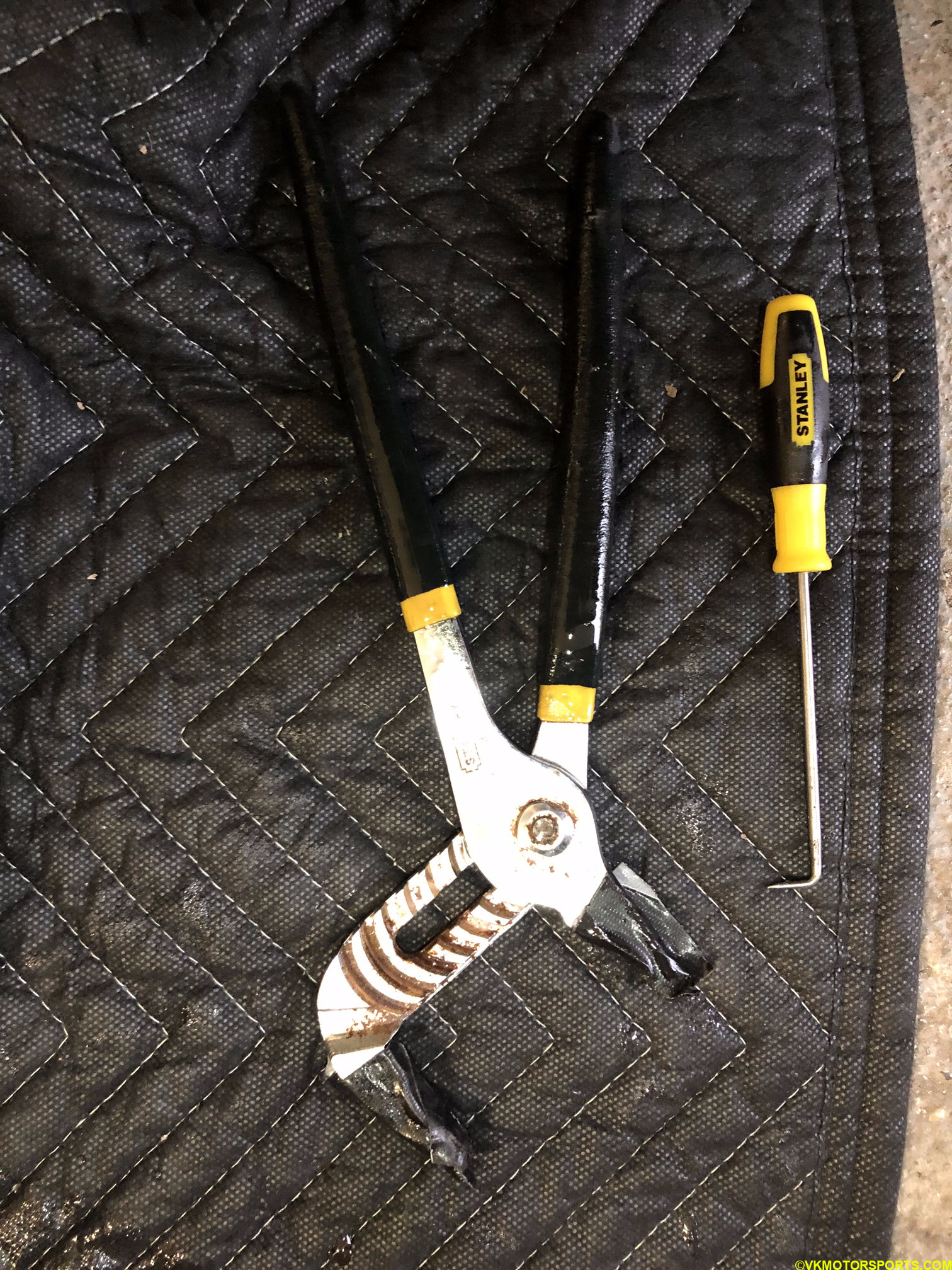 Figure 9. Pick and Channel Locks for removing hoses
Once you see the hose come out, it will leak a lot of coolant, and keep draining for a while. You may need to move the hose around every few minutes to let the coolant drain since it will pull the coolant from all the other hoses and the radiator area. Figure 10a shows the hose clamp being slid onto the middle of the hose and the hose draining coolant. Figure 10b and 10c shows both the large hoses detached from the water pump (red arrow) and the thermostat (blue arrow).
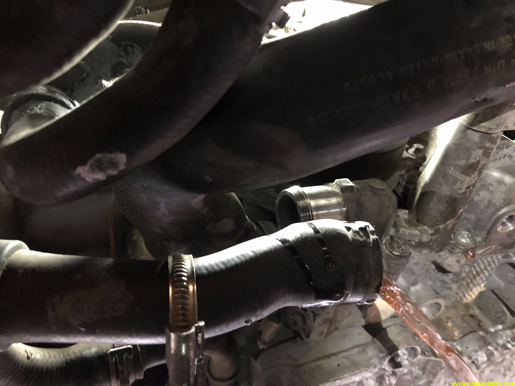 Figure 10a. Coolant draining from the large hoses
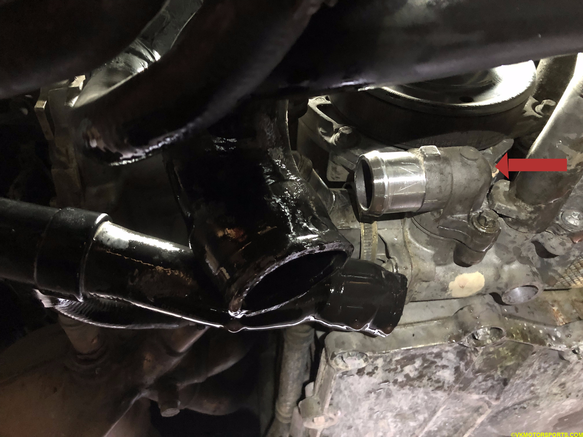 Figure 10b. Red arrow shows the water pump
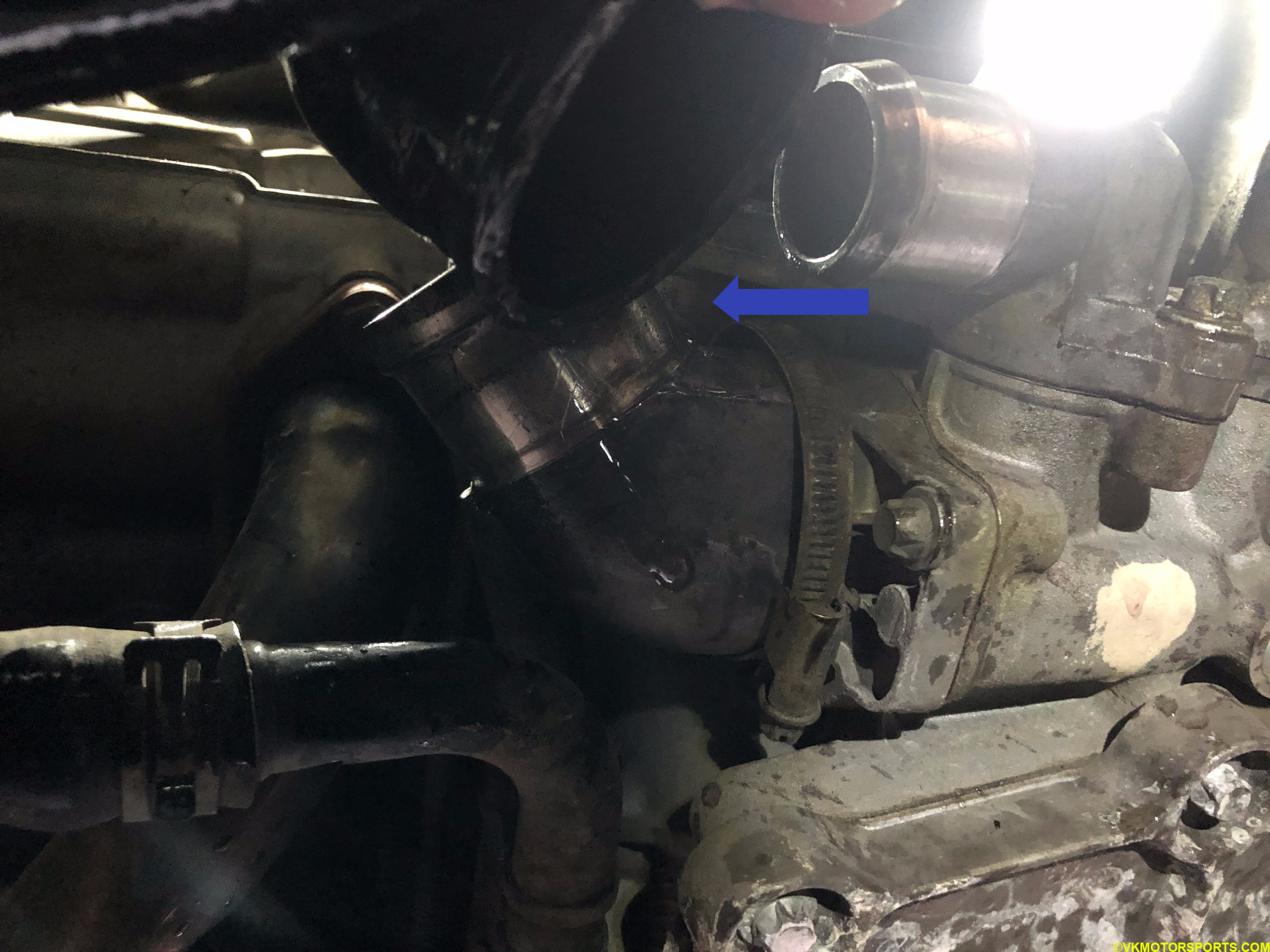 Figure 10c. Blue arrow shows the thermostat
Remove and Replace the Thermostat
A thermostat has 4 bolts (Figures 11a and 11b) that need to be removed. These bolts must be reused unless they are damaged, then they need to be replaced with the correct part. I ended up re-using my bolts since I had not purchased replacements. Some of these bolts are not easily accessible from under the car, so you may need wobble socket extensions which I used.
These bolts in the figures below are 8mm bolts since they are OEM so you will need an 8mm socket.
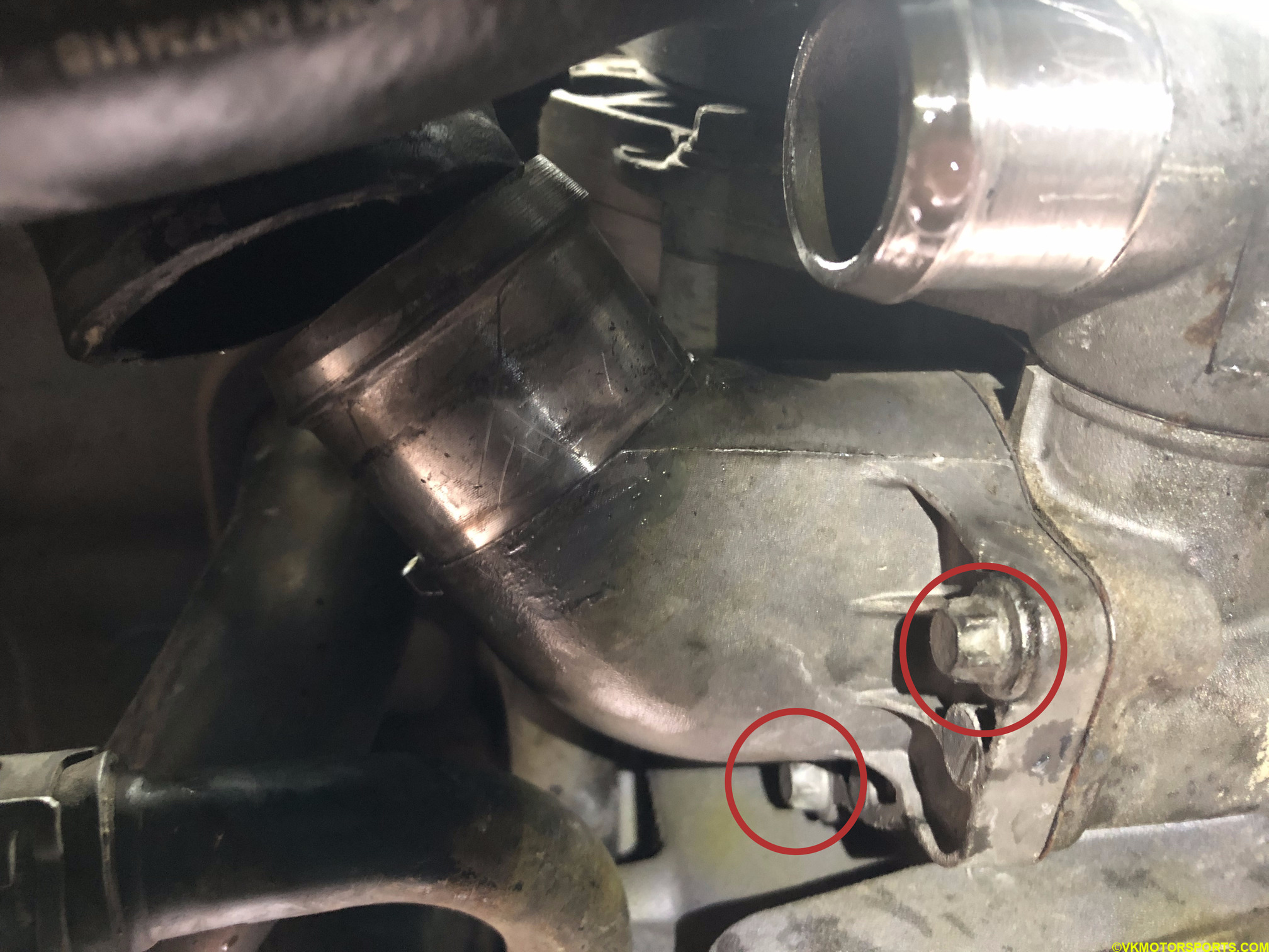 Figure 11a. Thermostat bolts to be removed
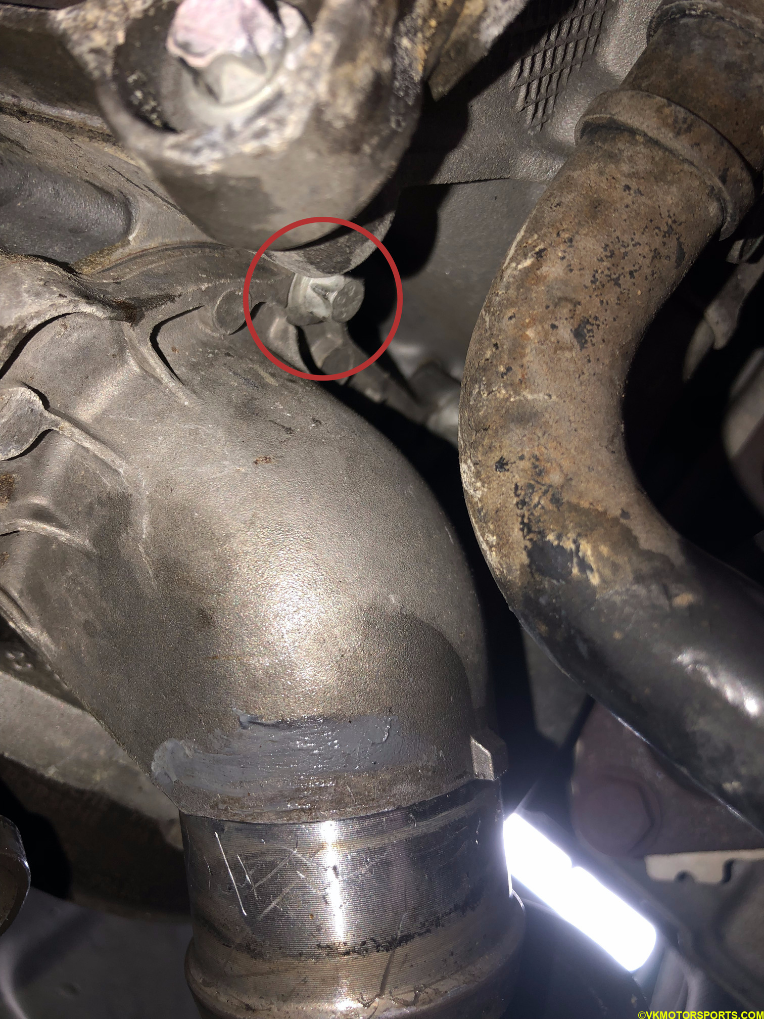 Figure 11b. Thermostat bolts to be removed
Once the thermostat has been removed as in Figure 12a you can see a thin metal gasket sticking to the body which must be pulled out with a flat screw driver. Figure 12b shows the old thermostat, the old gasket and the wobble socket extension that made it possible to remove those far back bolts.
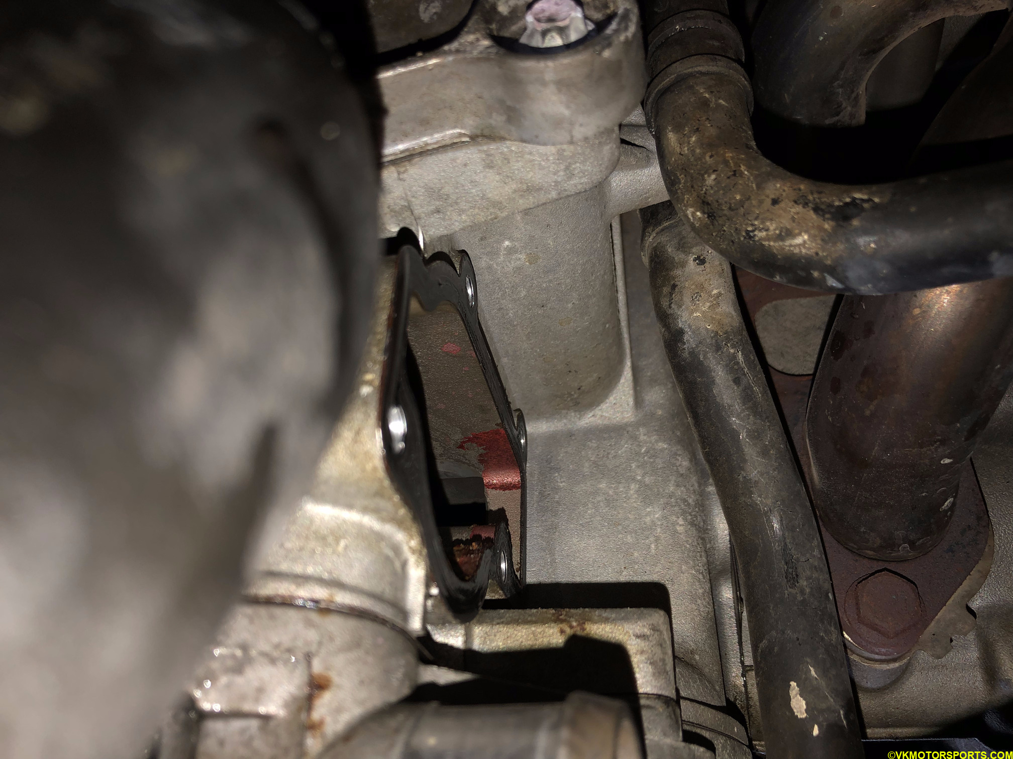 Figure 12a. Thermostat has been removed but the gasket remains
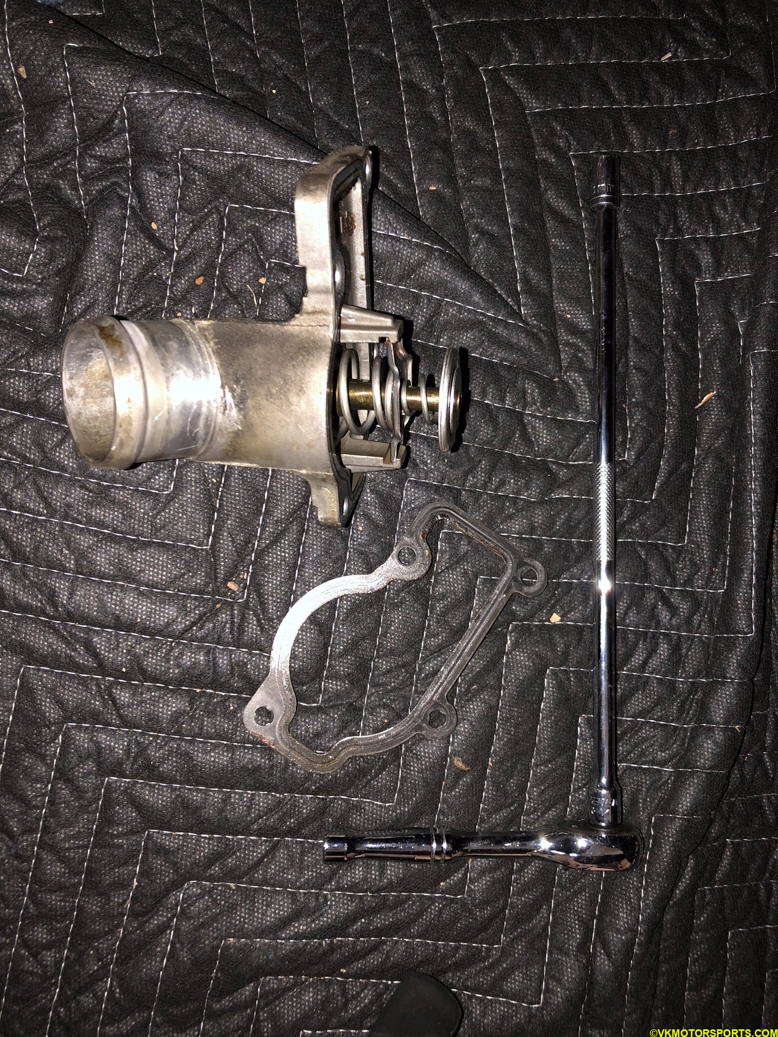 Figure 12b. Old thermostat, gasket, 8mm socket and wobble extension
New OEM model thermostat with cover and gasket Part# 996-106-013-61-M2 is shown in Figure 13a.
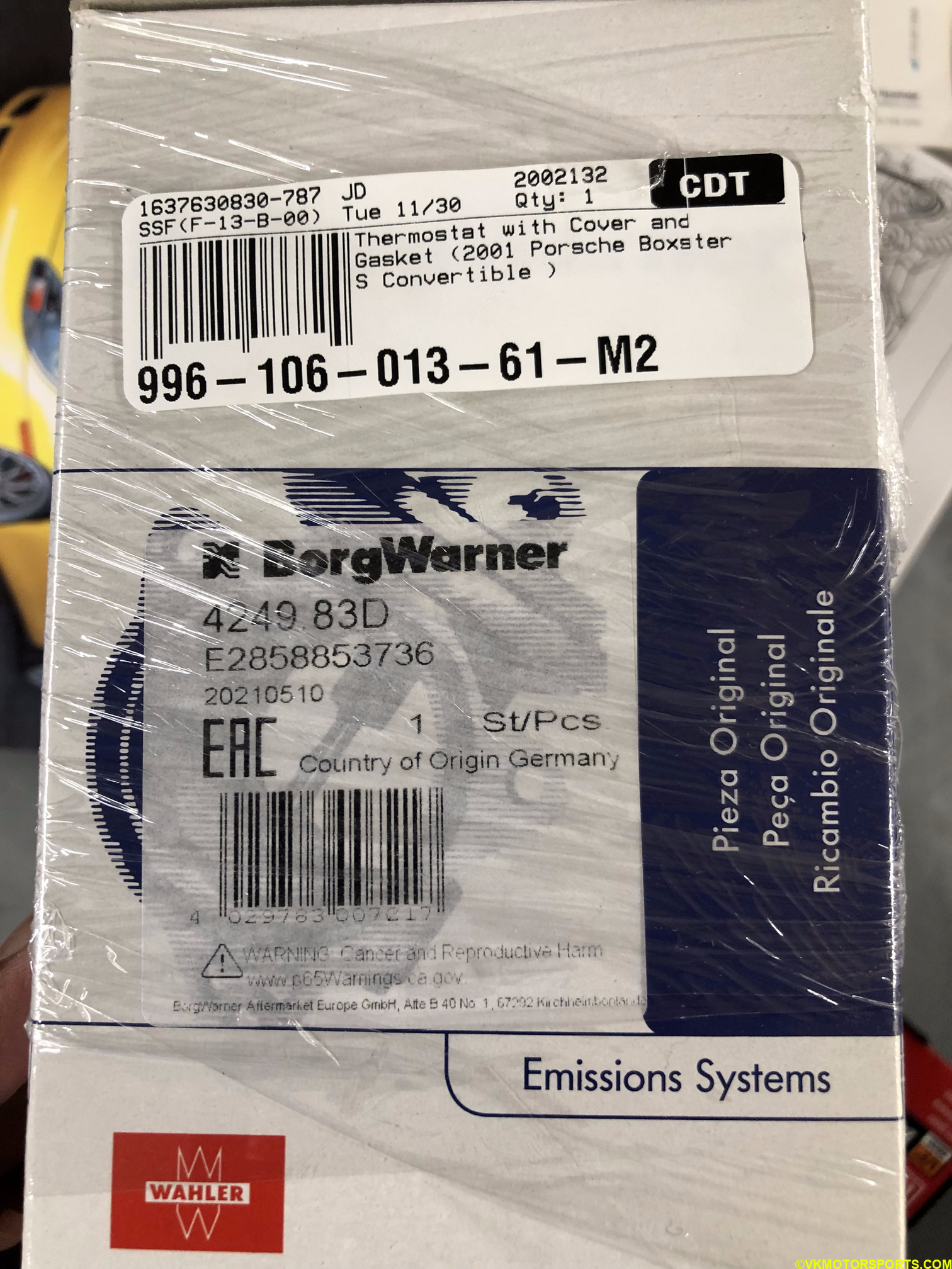 Figure 13a. New thermostat packaging for part# 996-106-013-61-M2
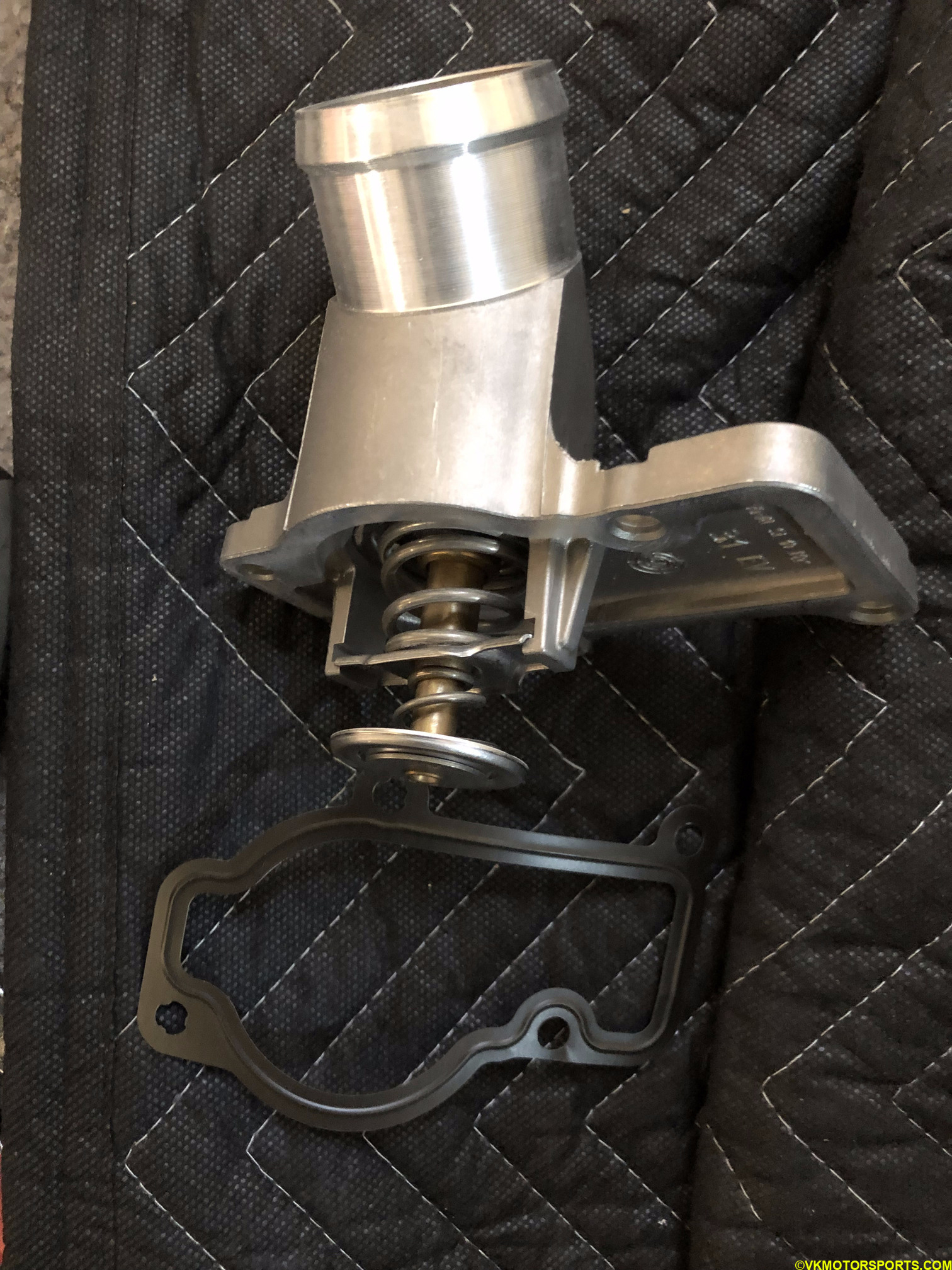 Figure 13b. Contents of thermostat package - new thermostat and new gasket
Installing the thermostat is the same as removing it, you need to place the gasket on the thermostat and bolt it to the engine. The bolt that was the farthest in was the hardest to get in. It is easier to do if your car is higher in the air. The torque specifications are 7 ft-lbs or hand tighten. Figure 14 shows the new thermostat has been installed but shows the bottom angle. Remember to use medium-strength blue threadlocker on all the bolts to prevent them from seizing.
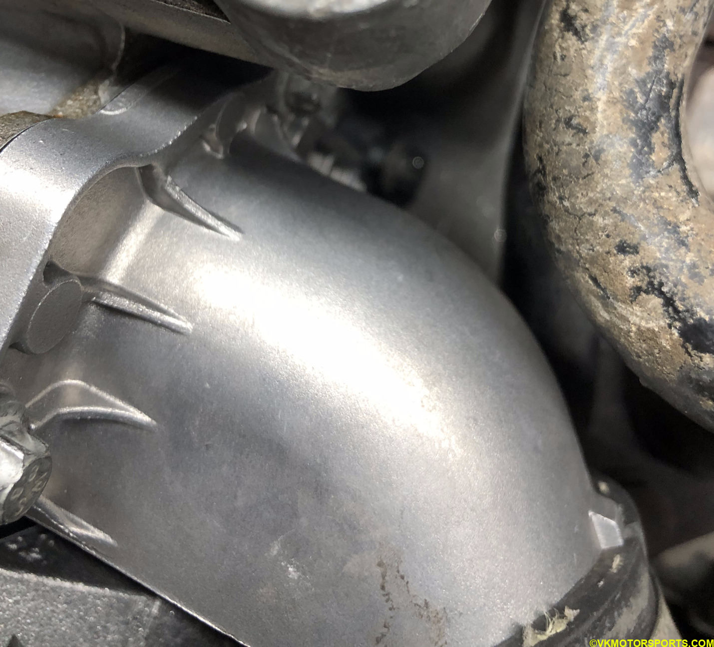 Figure 14. New thermostat has been installed
Open Up the Engine Cover
The 986 Boxster is a mid-engine vehicle so you need to open up the access to the engine from behind the seats. You do not need to take the seats out, as you can move them forward as much as possible and perform this task.
Open up the engine’s rear carpeting using the technique described in the air filter replacement post. Figure 15a shows the engine’s rear carpeting removed.
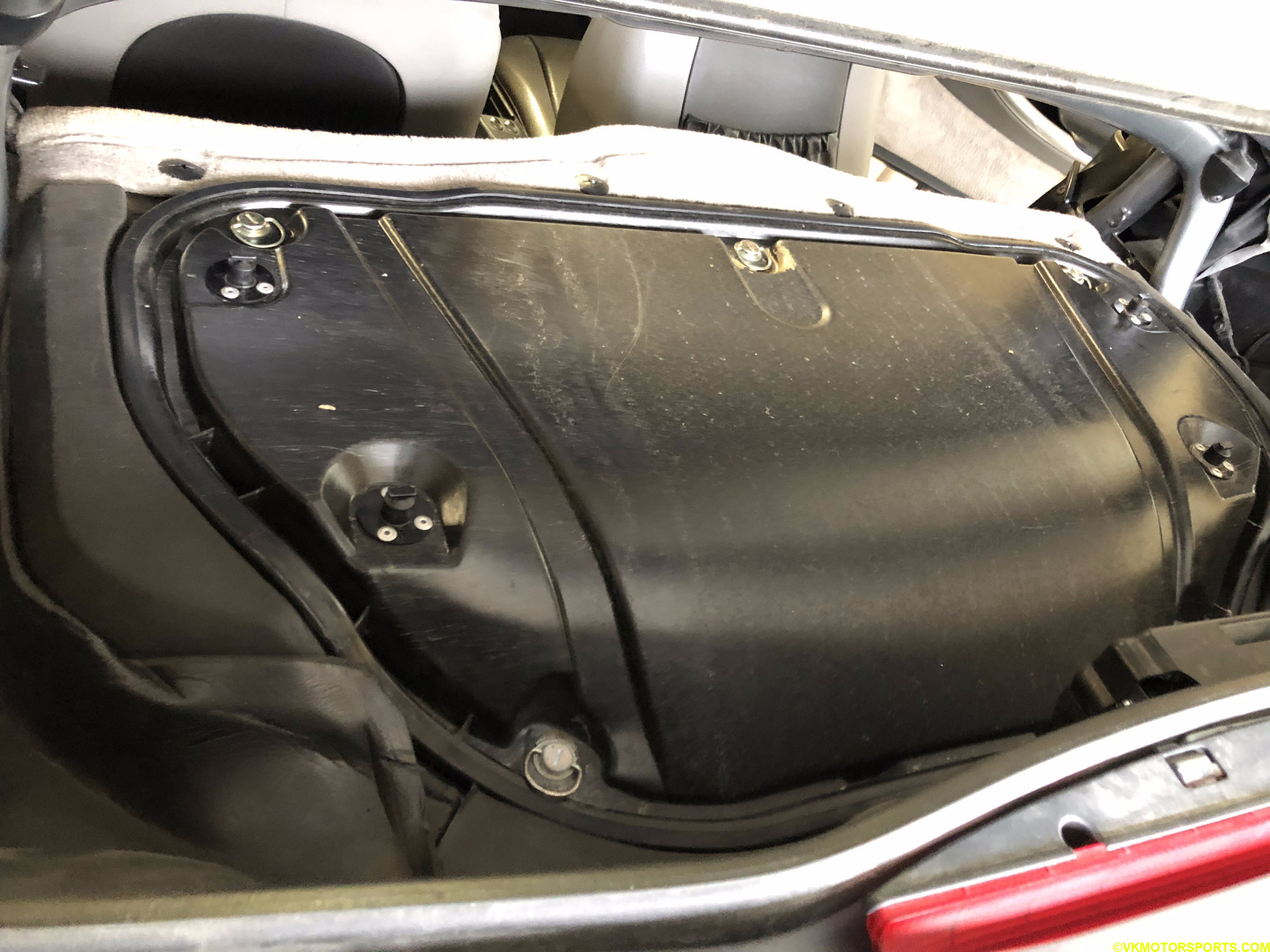 Figure 15a. Remove engine’s rear carpeting
To access the water pump and belt-pulley system you must pull the seats forward and remove the engine’s front cover. For that you have to first remove the carpeting by removing the trim screws circled in red in Figure 15b and then pull the carpet away as shown in Figure 15c. This will expose the metallic engine shroud (cover) as shown in Figure 16a.
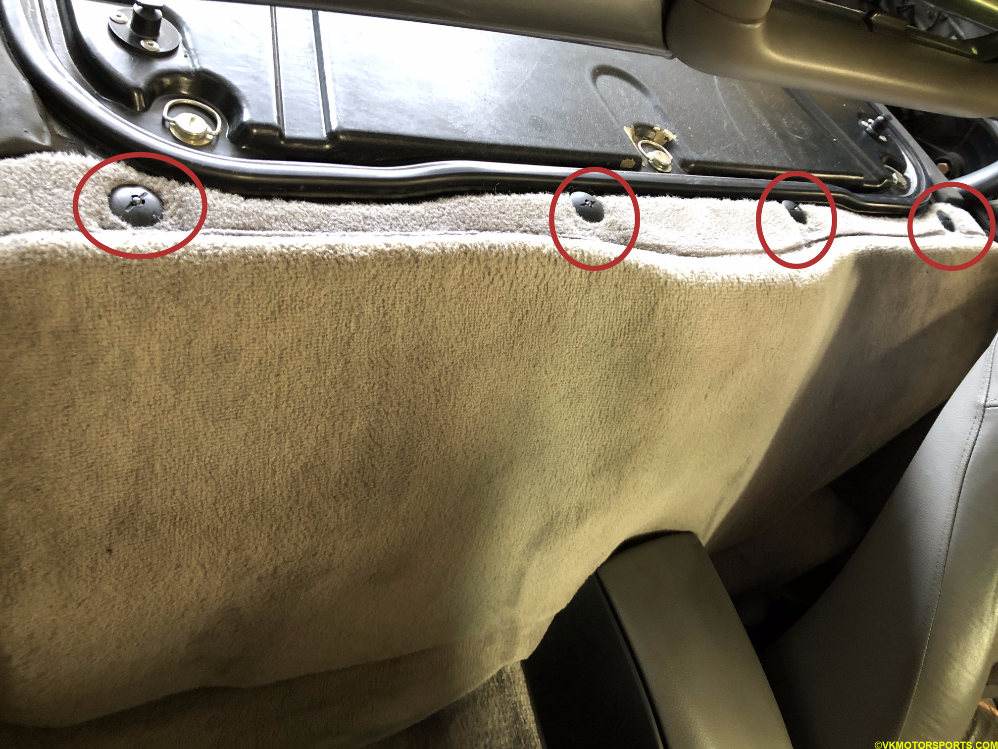 Figure 15b. Open the trim screws circled in red
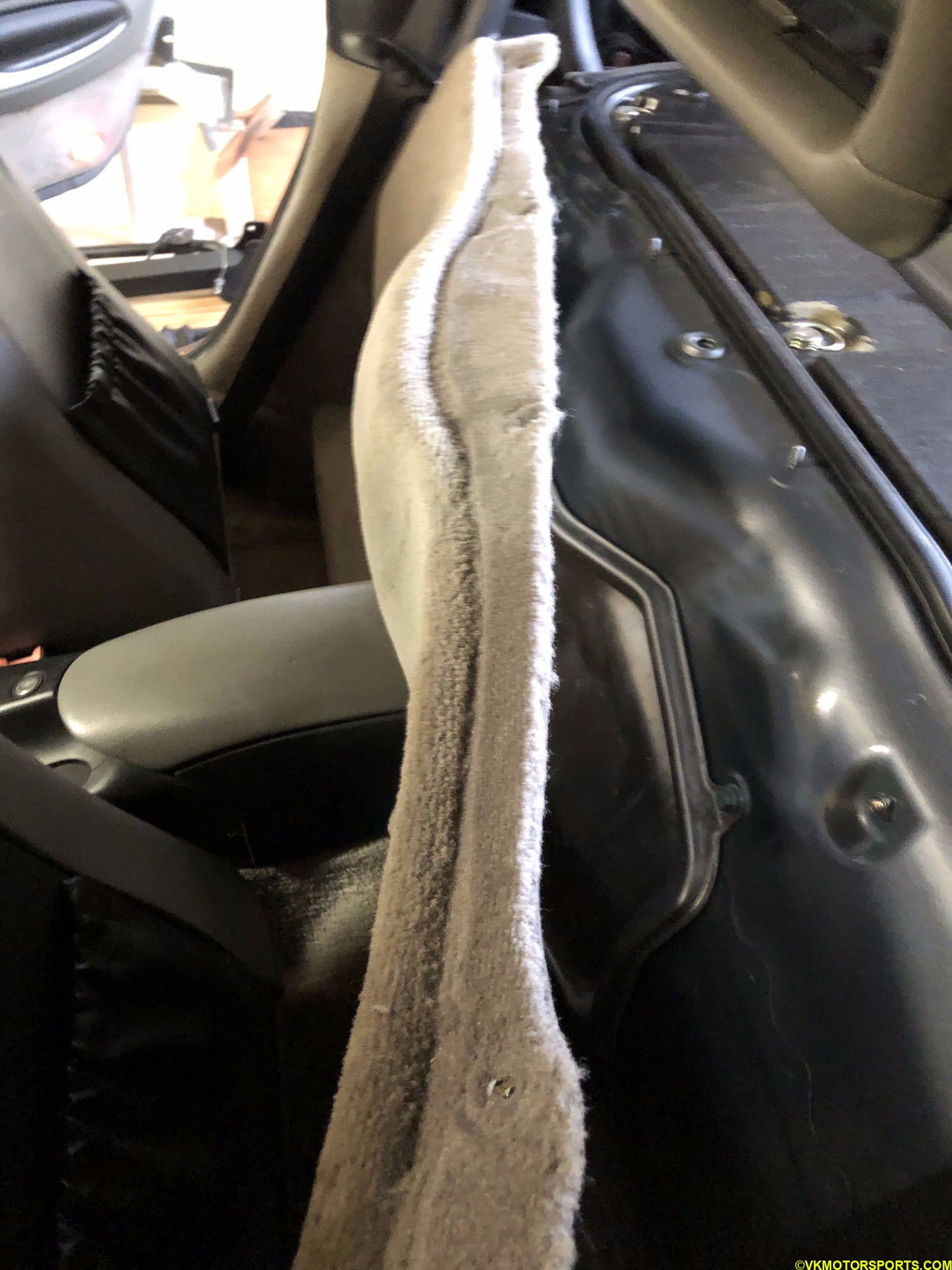 Figure 15b. Pull the carpet away
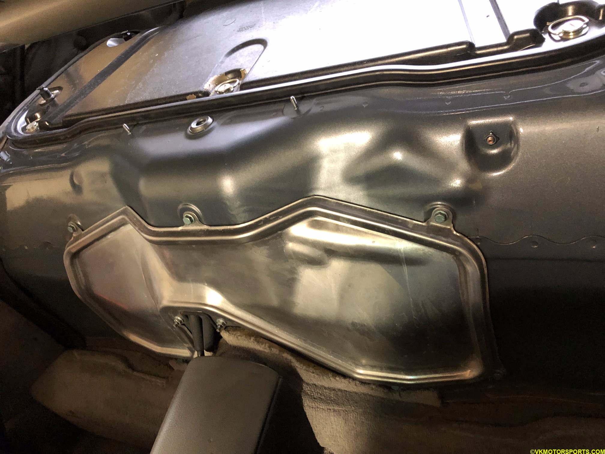 Figure 16a. Engine front cover/shroud
NOTE: Wear gloves while doing this as the metal shroud has sharp edges and may cut your hands.
Using a 10mm socket open all the nuts and carefully pull away the metal shroud (Figure 16b) to expose the belt and pulley system as shown in Figure 16c. The water pump is at the bottom left. Take photos of the way the belt goes over the various pulleys since you will need to replicate this same formation when you install a new belt, described in a later section.
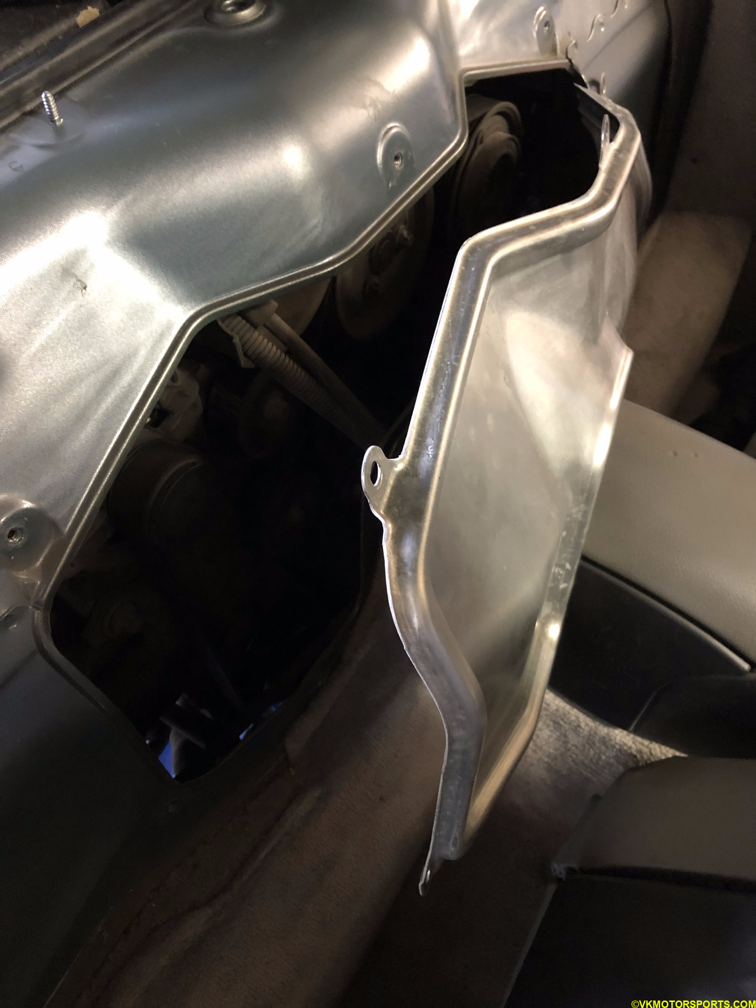 Figure 16b. Pull the shroud away
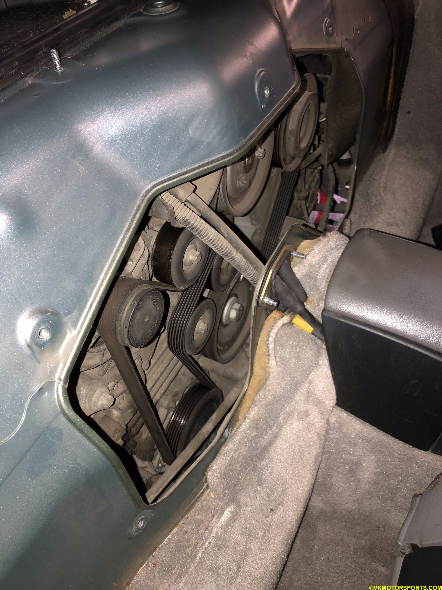 Figure 16d. Belt-pulley system with the water pump
Remove the Belt
Next we need to remove the belt first. Using a short 24mm socket and a 1/2” drive breaker bar, you can loosen the nut in the middle pulley (Figure 17), which is the tensioner and the only one with a 24mm size nut. You do not need to open the bolt fully, but just pull it towards the right (clockwise) and the belt will lose its tension. Then while holding the breaker bar with your right hand, pull the belt off any other pulley with your left hand. Figure 17 shows that I have pulled the belt off one of the top pulleys. Carefully remove the belt off the other pulleys and take it out.
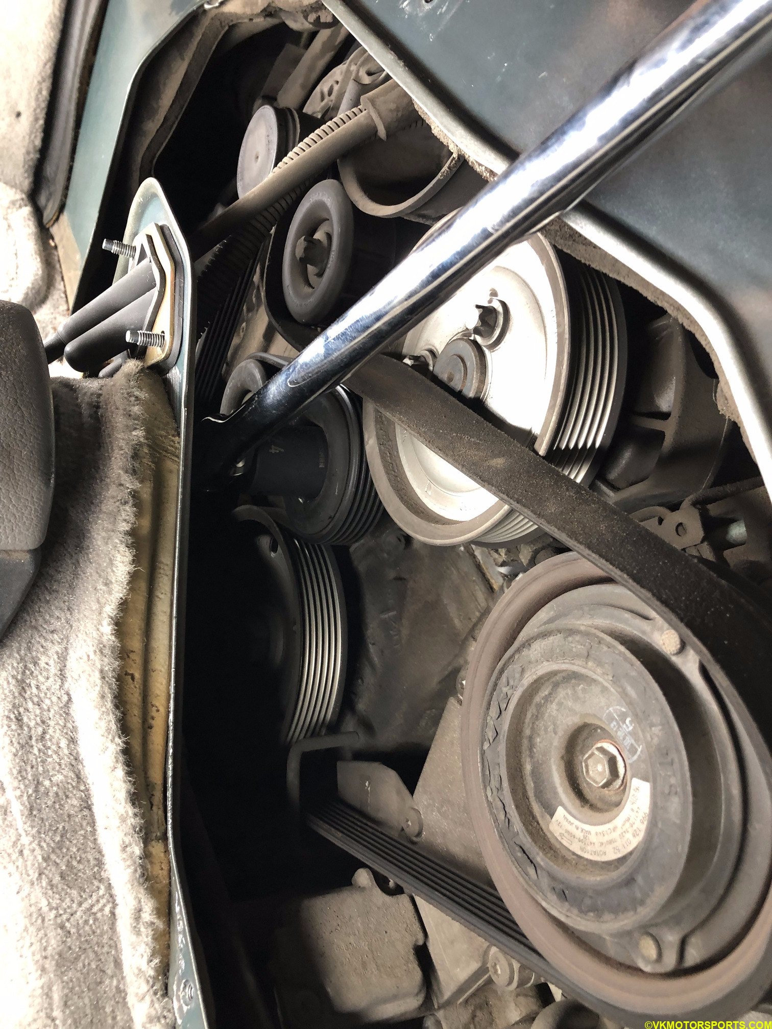 FIgure 17. Loosen the tension with a breaker bar and 24mm socket
Now that the belt has been loosened, slide it off the water pump’s pulley (Figure 18). It is time to remove and replace the water pump.
If you are changing the belt, then take off the belt completely, otherwise leave it on.
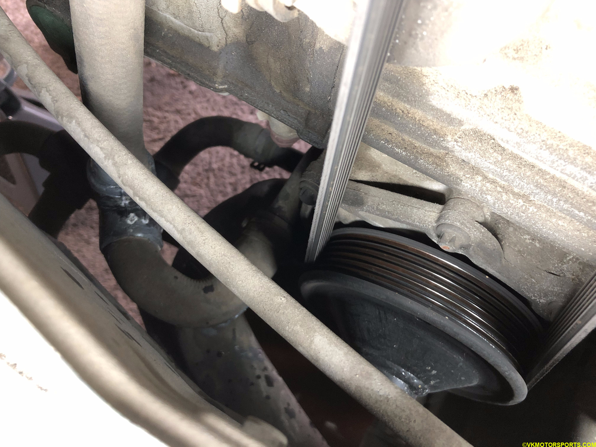 Figure 18. Top view of the water pump
Remove and Replace the Water Pump
The water pump has 7 bolts that connect it to the engine crankcase, 4 to be accessed from the top (Figure 19a and 19b) and 3 from the bottom (Figure 19c). The most difficult bolt to take out was the innermost one shown in Figure 19d. I had to make a contraption with duct tape, a short wobble socket extension and a socket to be able to slowly unscrew it, but once that was done, I could use by skinny hand to unscrew it.
These bolts are also 8mm bolts, but the new replacement bolts I received were 10mm bolts.
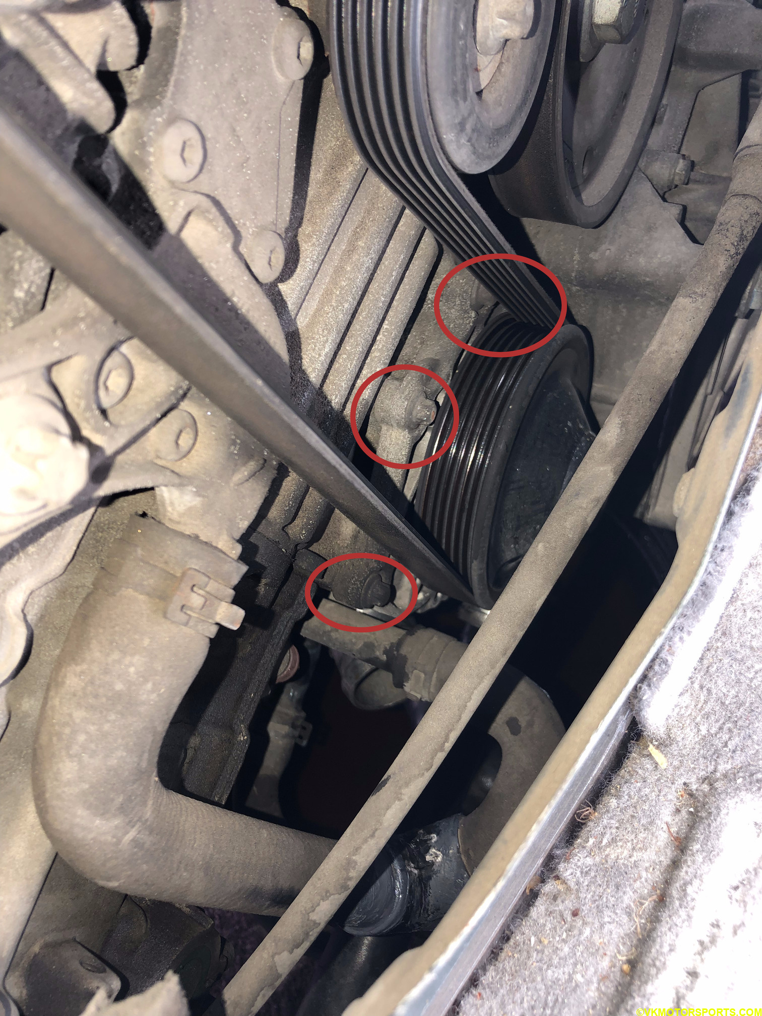 Figure 19a. Location of the top 4 bolts connecting the water pump to the engine crankcase
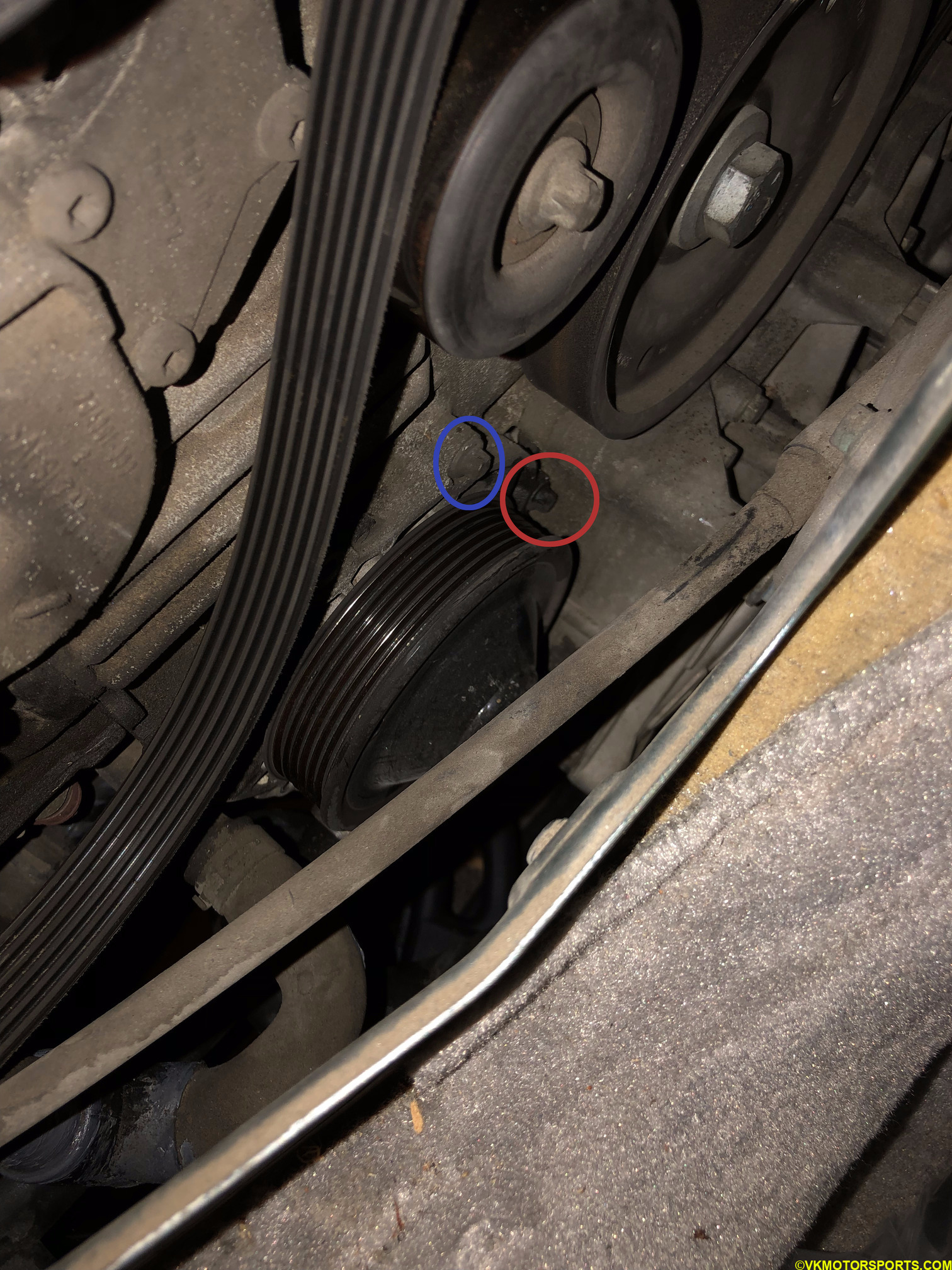 Figure 19b. Close-up of the 2 bolts in the back once belt is removed
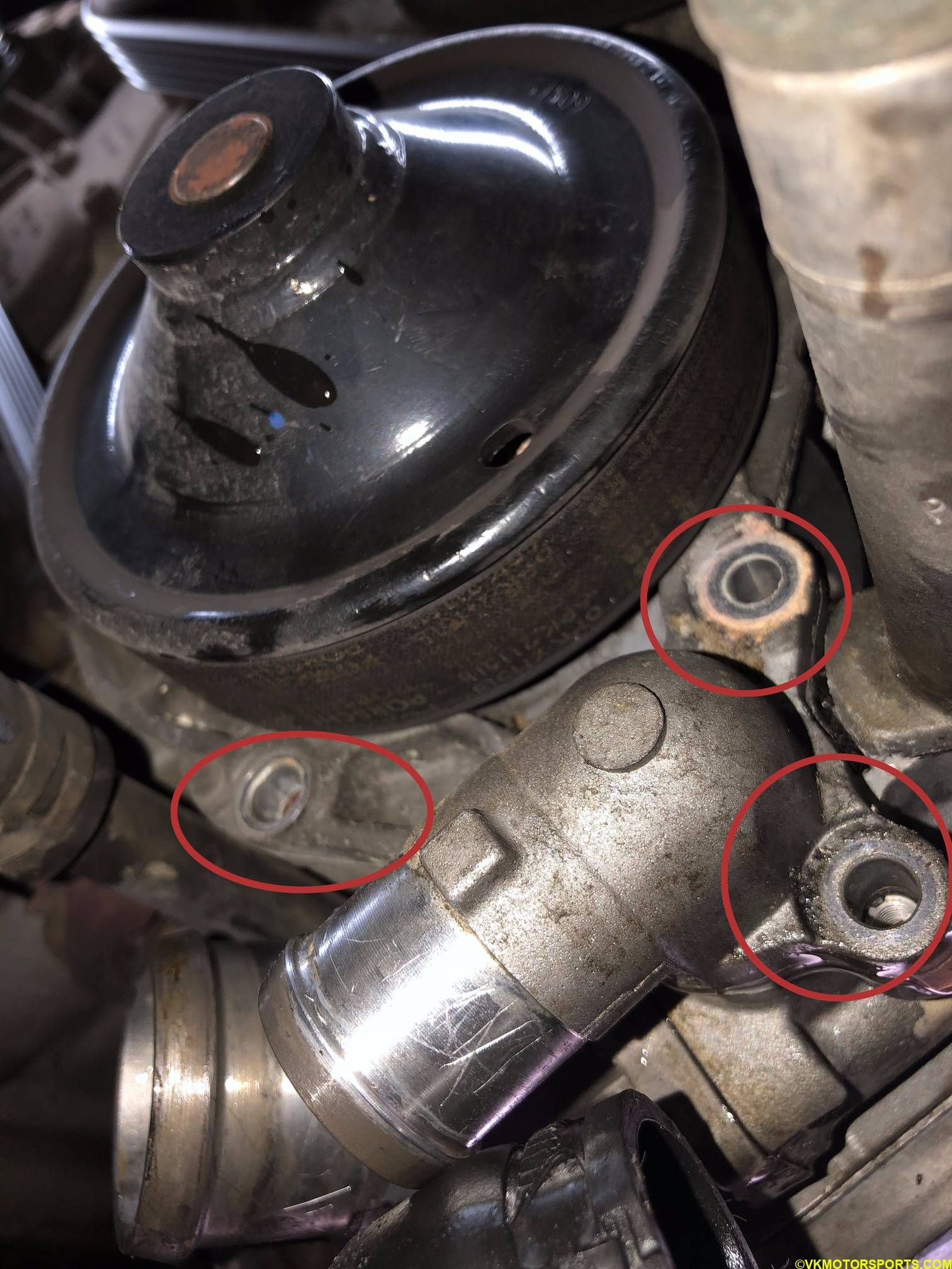 Figure 19c. 3 bolts to be accessed from the bottom
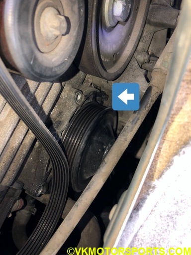 Figure 19d. Most difficult bolt to remove
Some of the bolts were undergoing corrosion (Figure 20), so it is recommended to use new bolts for the full pump. Luckily the water pump kit came with new bolts for the pump. Two of those bolts are longer than the other five. Note their positions when you take out the pump. These two long bolts are the ones you should use first while installing the replacement/new pump on engine crankcase.
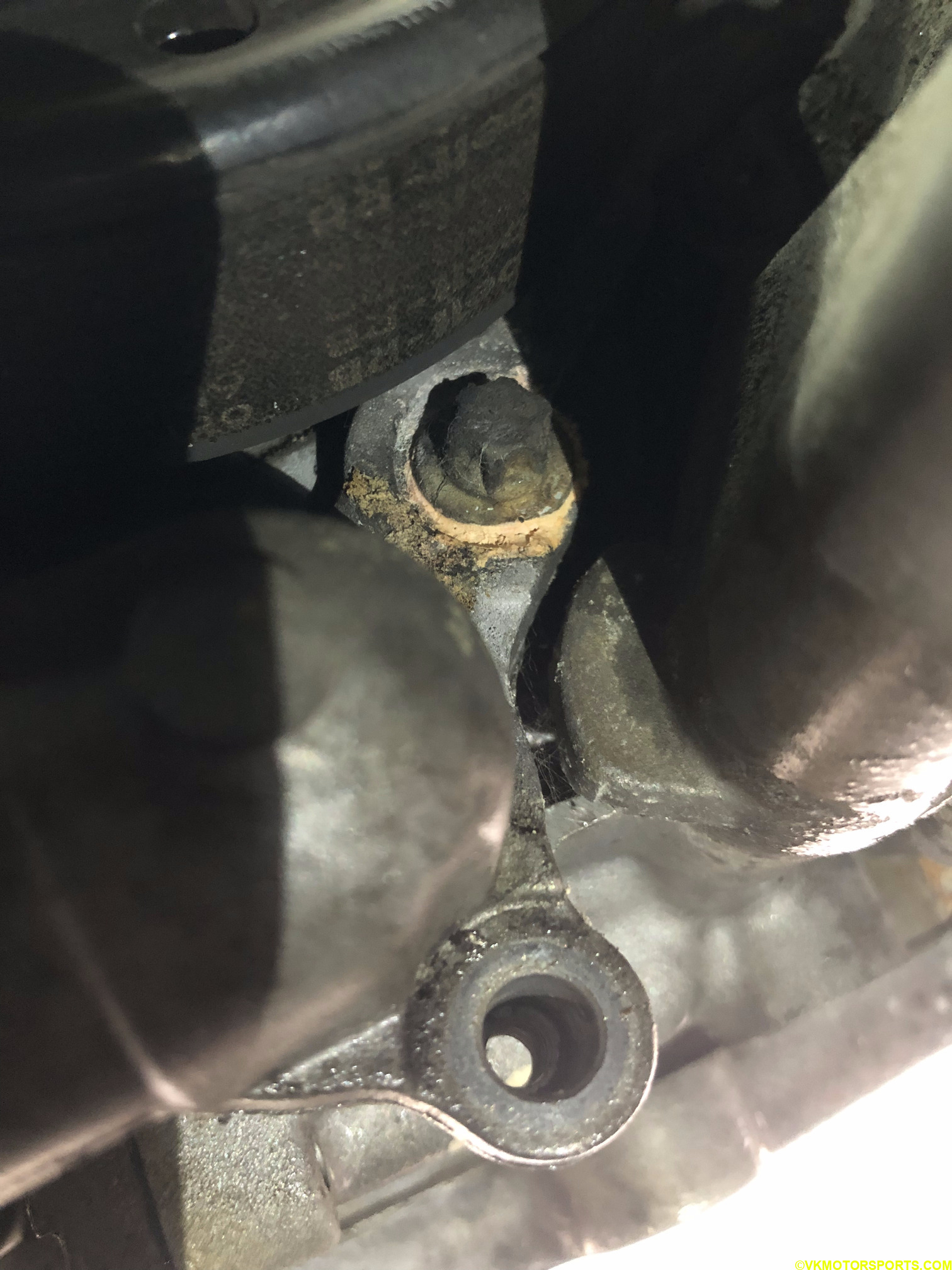 Figure 20. Corroding bolt on the water pump
Once all the bolts have been removed, you will be able to pull the water pump off the engine crankcase, as seen in Figure 21, and then slowly lift it up. Do not drop it ! The water pump gasket may be connected to another part on the engine crankcase, since it is a joint gasket if it is an OEM gasket (Figure 24a), and you have to move the water pump back and forth to break away. Or if you have a friend, you can have them hold the water pump while you go under the car and cut the joint part of the gasket.
The astute reader may notice the black colored gasket is visible behind the water pump bolt holes, in Figure 21.
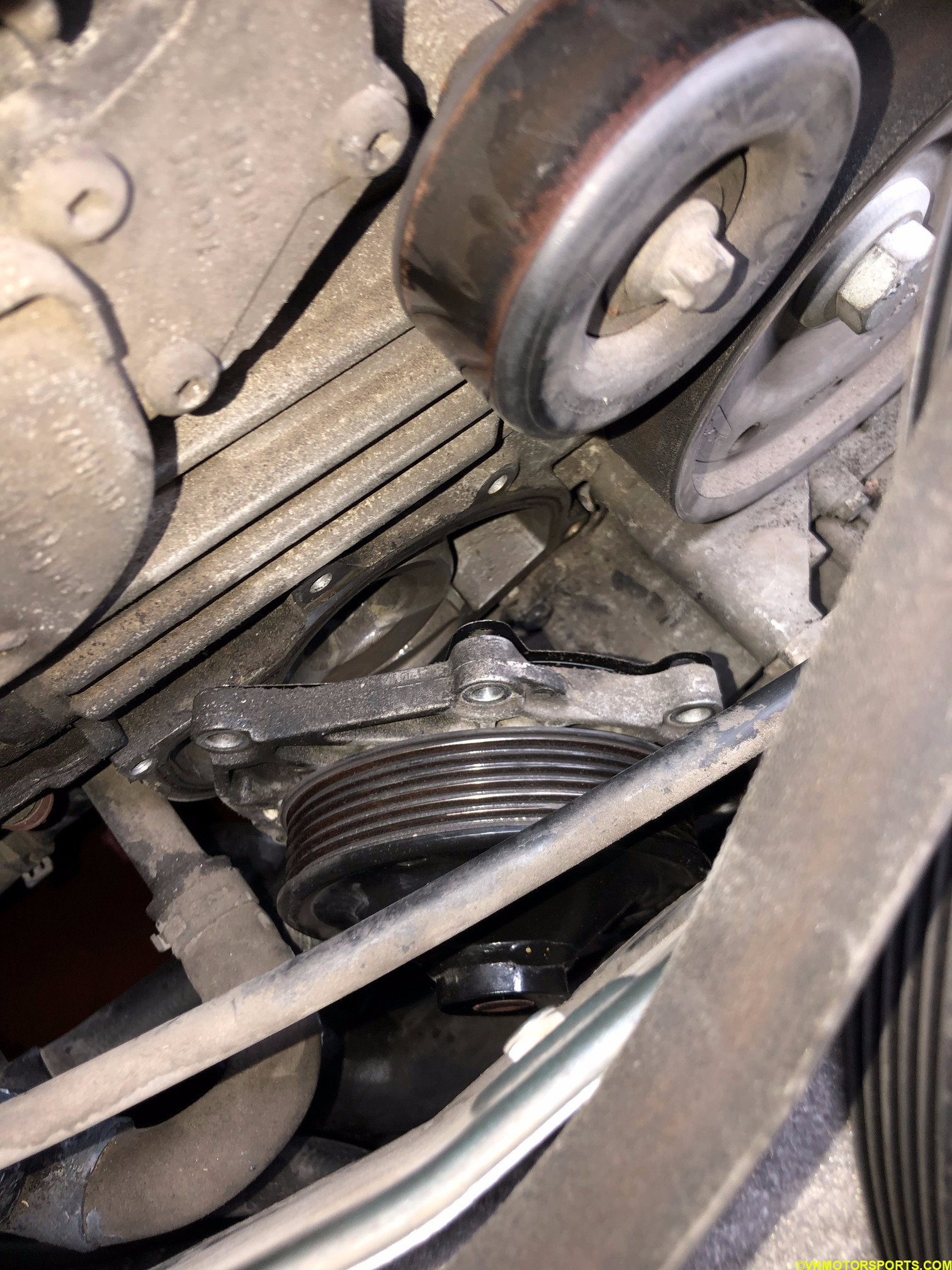 Figure 21. Pull water pump off engine crankcase
Once the water pump is removed, look for debris present from the gasket and wipe it off with a shop towel or clean rag. Figure 22 shows a relatively clean area where the water pump was attached to the engine crankcase.
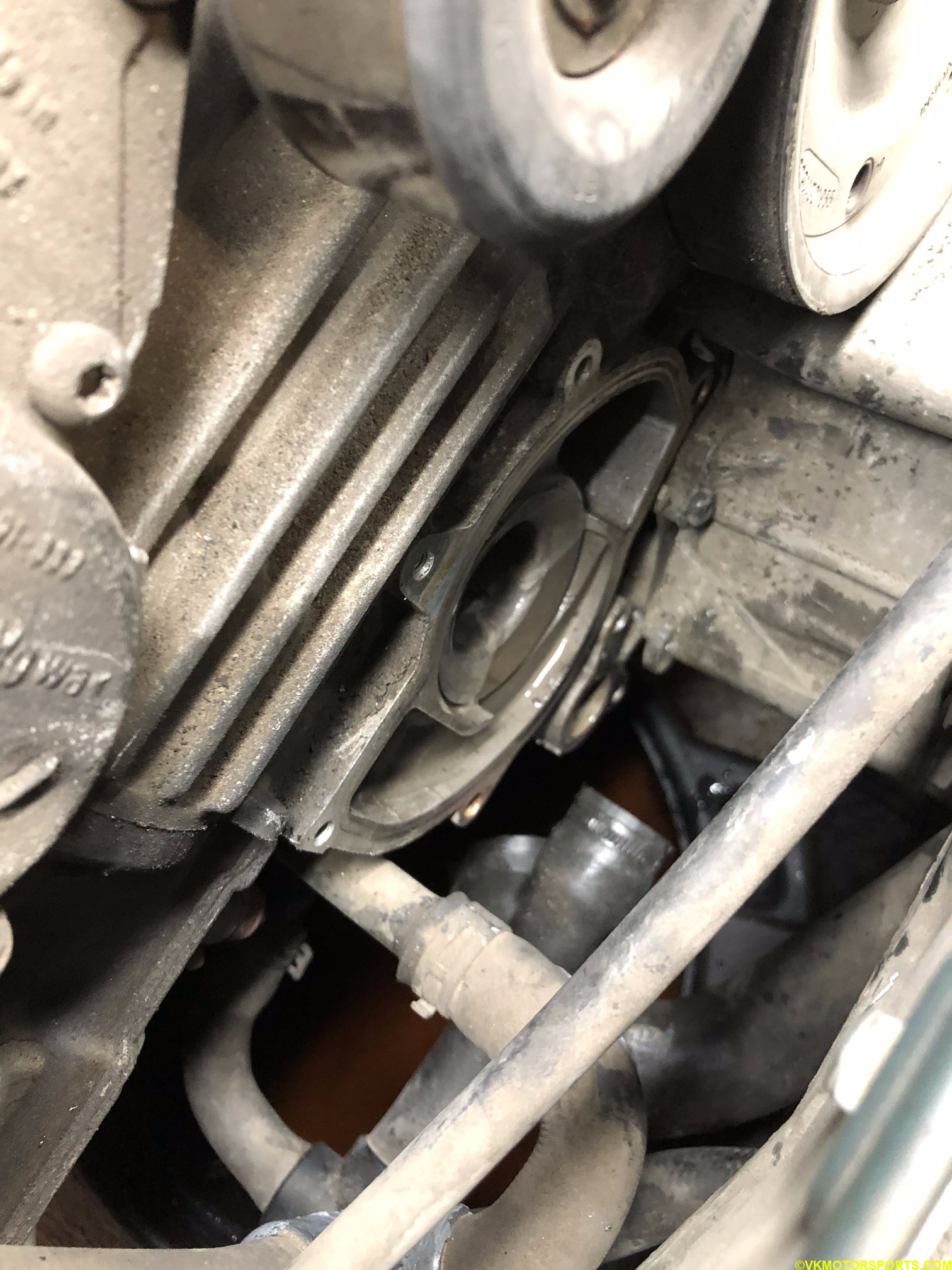 Figure 22. Water pump has been removed
Figure 23 shows the water pump and the gasket that I removed. Surprisingly the gasket was all bent. I tried spinning the water pump pulley and it did not spin. It also looks like the gasket got bent while I was trying to break it away from the rest of the engine. In comparison, on the new water pump the pulley could be spun freely by hand. Changing the water pump was the right move !
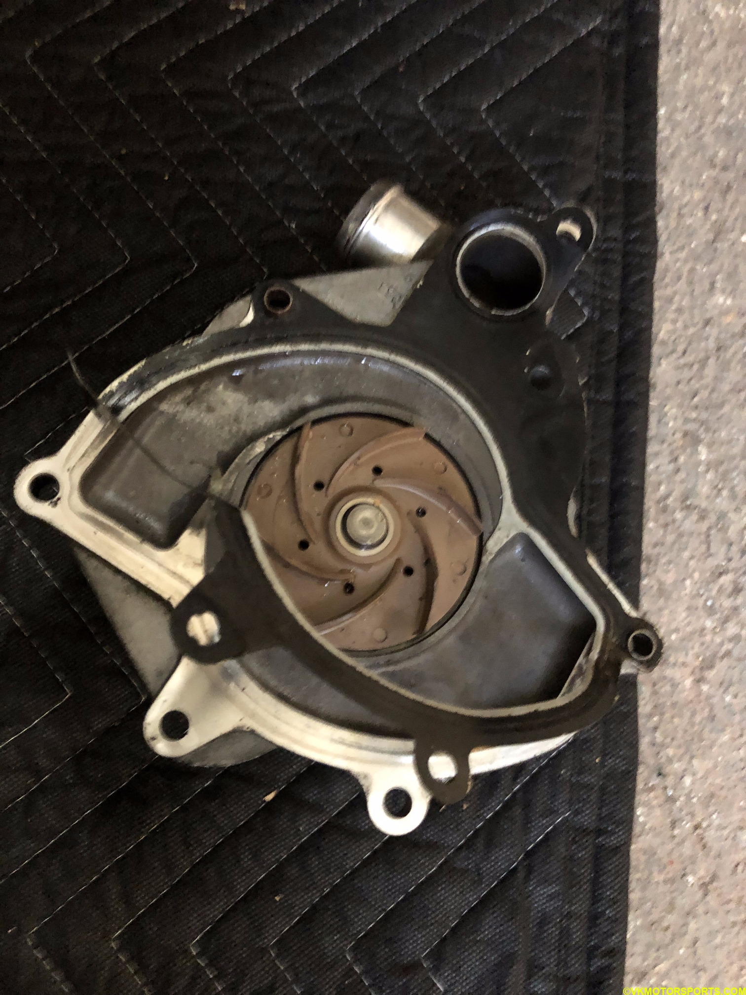 Figure 23. Old water pump and bent gasket
The new water pump is part# 996-106-011-57-M100 and the gasket is part# 996-106-340-54-OEM. Place the gasket over the 2 ends of the water pump with protrusions where the gasket will lock in as shown in Figure 24a. The gasket is a joint gasket with another part, so we break the parts of the gasket that we do not need as shown in Figure 24b.
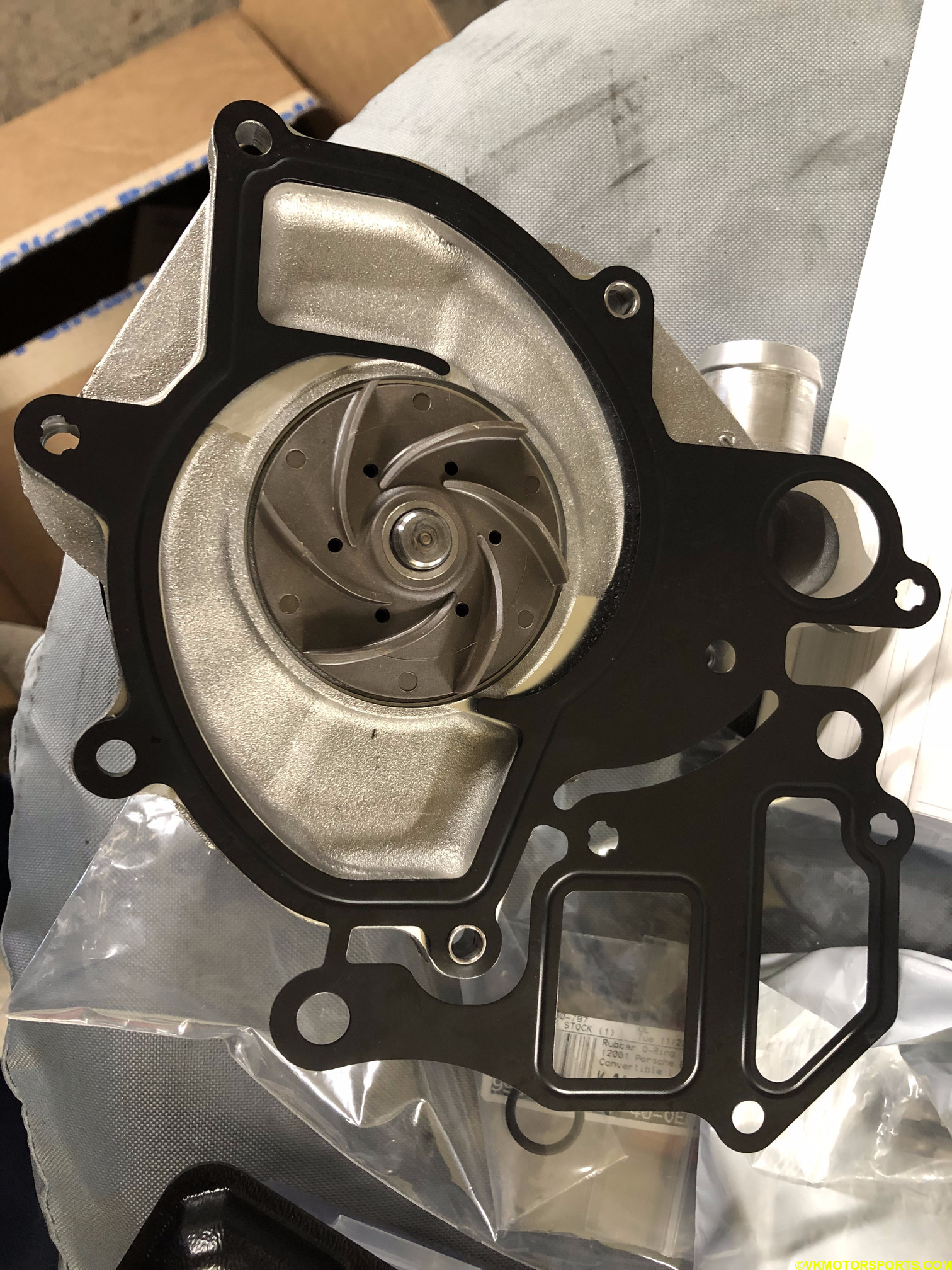 Figure 24a. New gasket attached to the new water pump
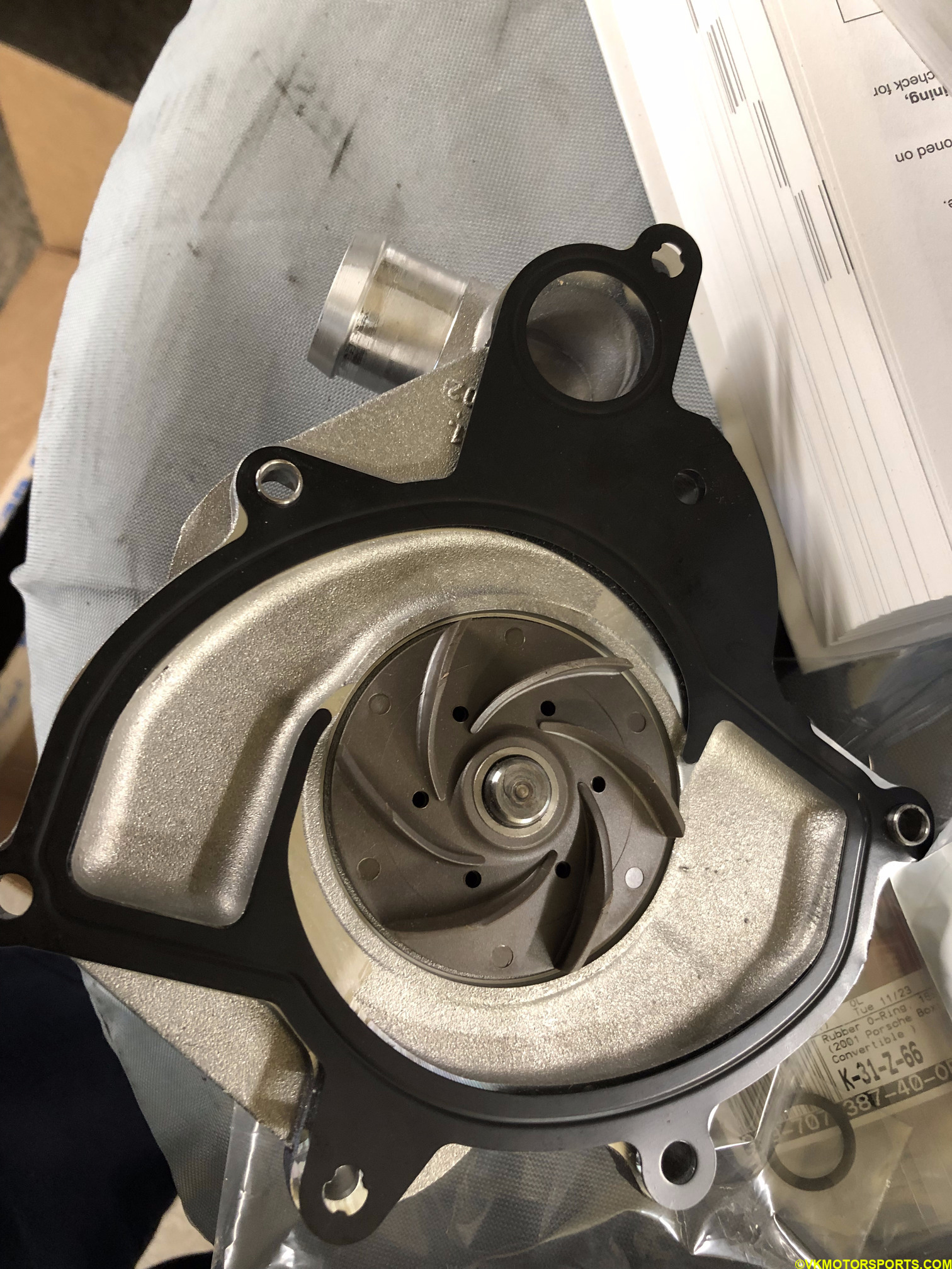 Figure 24b. Cut the extra gasket away to make gasket fit perfect
Now install the water pump back on to the engine crankcase. Start with the two long bolts first and then do the rest of the bolts. The torque spec is 7ft-lbs so you can just hand tighten them. Figure 25 shows the water pump installed with the new bolts. Remember to use medium-strength blue threadlocker on all the bolts to prevent them from seizing.
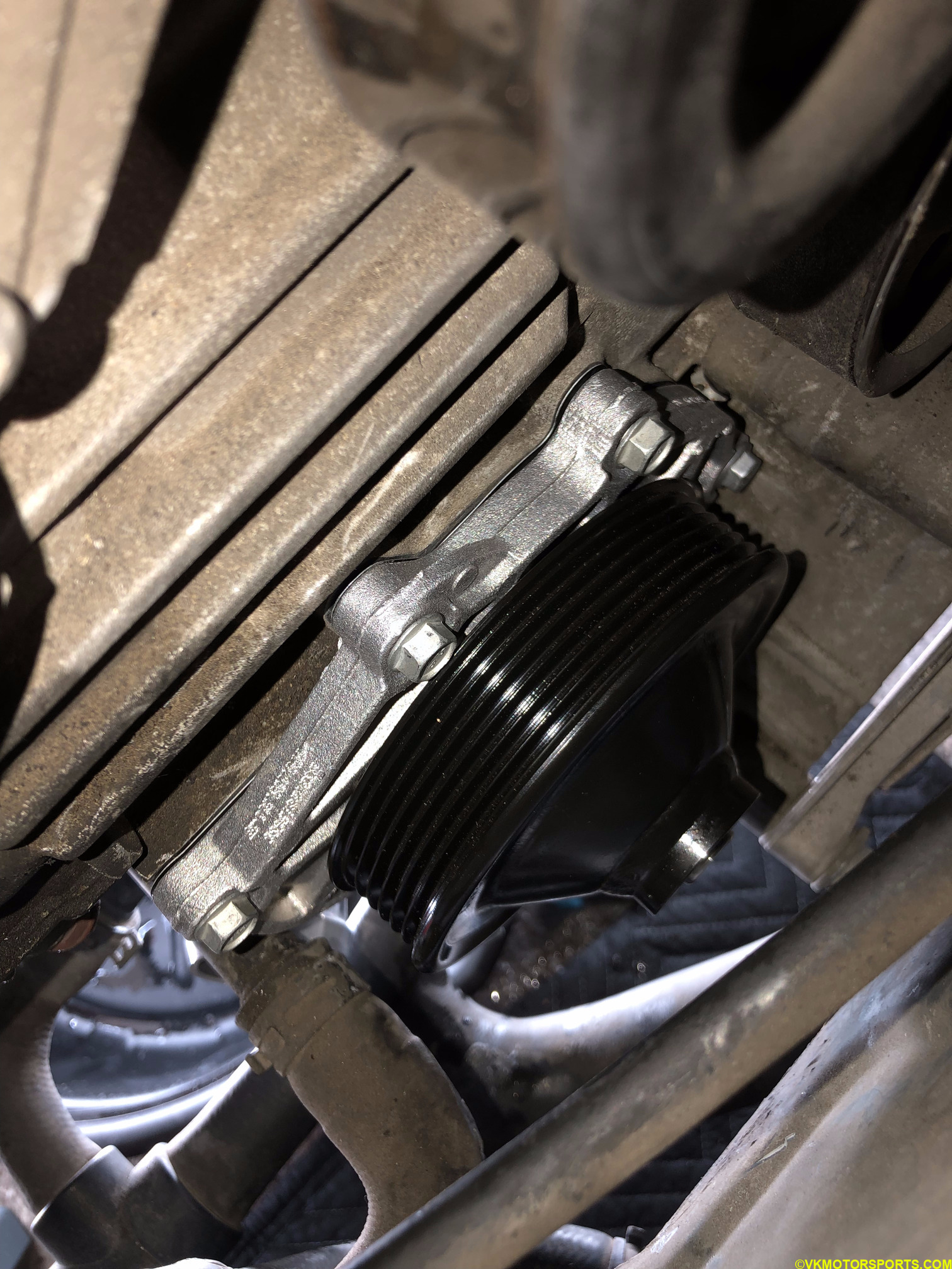 Figure 25. New water pump installed with new bolts
Reinstall Belt
Now we need to install the belt back on. I used the OEM belt part# 996-102-151-66-OEM (Figure 26) for this. Even though my belt did not look like it needed replacement, I did it anyway and do not need to worry about it for the next several thousand miles.
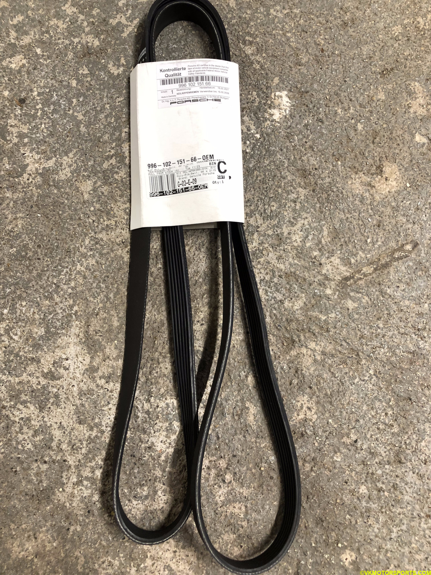 Figure 26. Belt part# 996-102-151-66-OEM
When you are installing the belt, start with the water pump. You may have to go under the car to make sure that the belt is wrapped around the pump’s pulley correctly. Figure 27a shows the belt on the water pump from under the car.
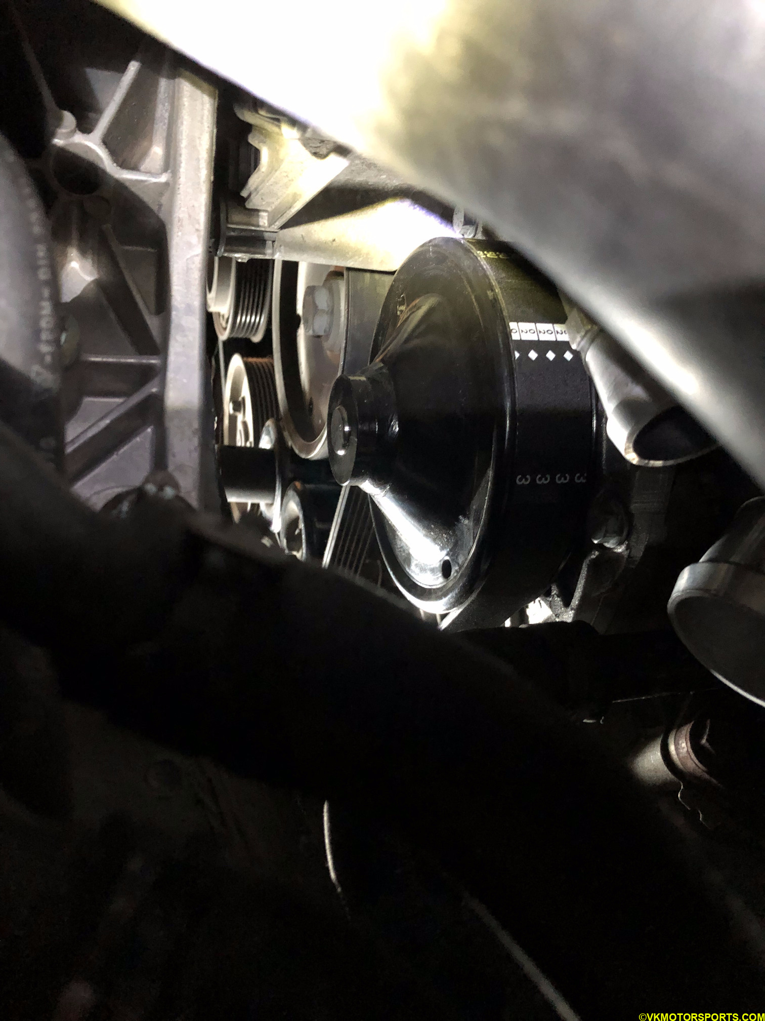 Figure 27a. Under-car view of the belt on the water pump
Follow the same procedure of removing the belt, to install the belt and make sure you set it up correctly as it was before you removed it. The belt flows logically over the pulleys - the ribbed parts of the belt touch the grooves of the pulleys and the smooth parts of the belts touch the pulleys that have no grooves.
To adjust the tensioner you may need the 24mm socket and breaker bar to allow the belt to fit nicely, as shown earlier in Figure 17.
The below figure shows the belt fully installed. Before we test the belt has been correctly installed, let’s replace the hoses or connect them back if you do not want to replace them.
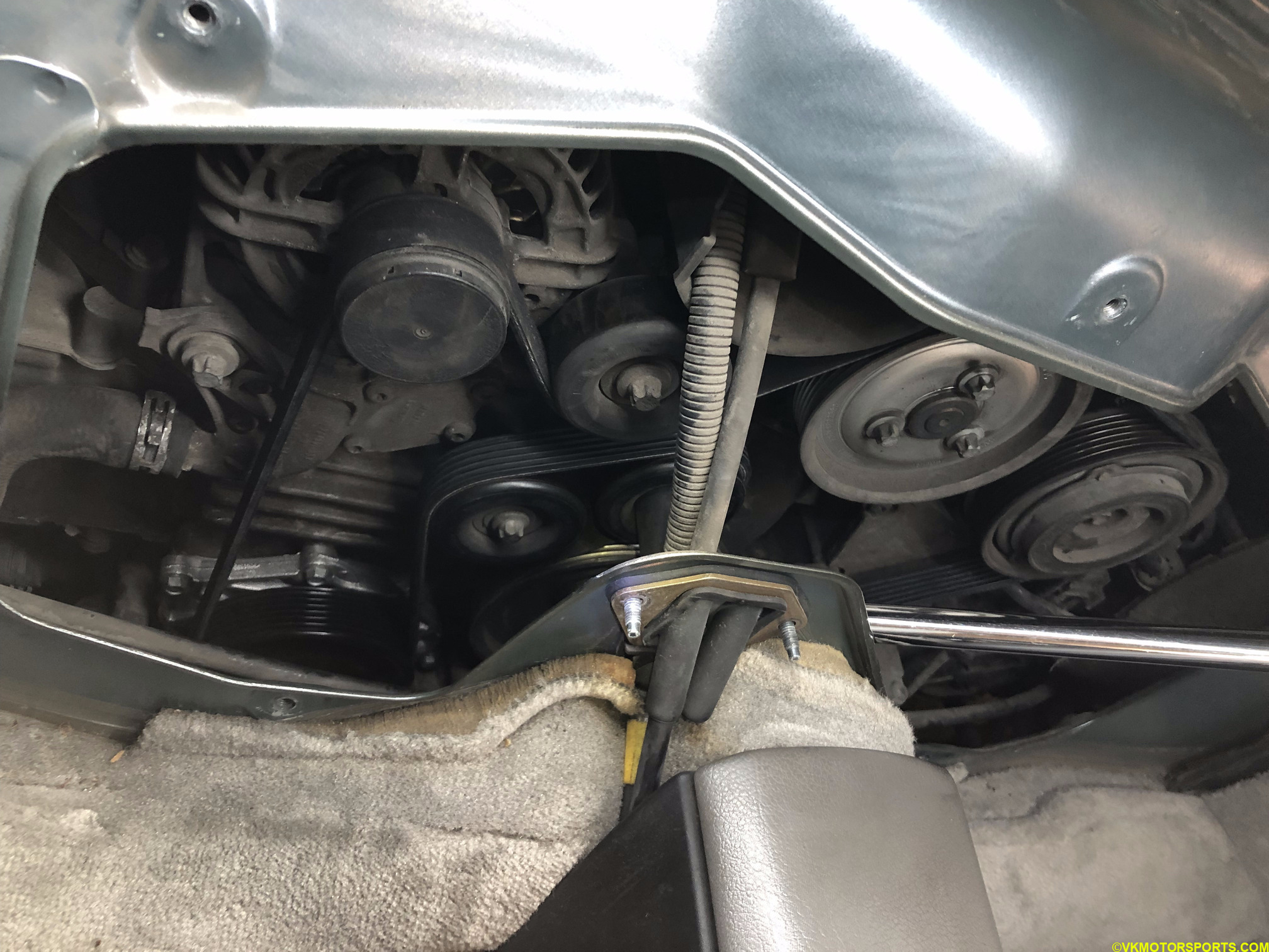 Figure 27b. The belt is now fully installed
Replace the Hoses
If your large hoses are bad or look old, it is a good time to change them at this time. Using the same tools as in Figure 9 and some effort you can remove the full hose and replace them with new ones with part numbers as below:
- Water Hose to Water Flange at Oil Pump Housing (Large Hose) Part#
996-106-501-07-M253 - Water Hose - Thermostat housing to water pipe Part#
996-106-502-06-M253
NOTE: Remember to tighten with new appropriately sized hose clamps after you have tightened the hose.
I also changed the cracked hose (view from under the car in Figure 28a) as it is connected to the engine block (view from the engine bay shown in Figure 28b) and required a lot of effort to get it out. The procedure is the same but the clamps were really painful and needed a spare set of hands. Since I had a replacement hose part# 996-106-212-12 (Figure 28c), I cut the old hose out, slid the clamps out of the engine body with force and then used new clamps on the hose.
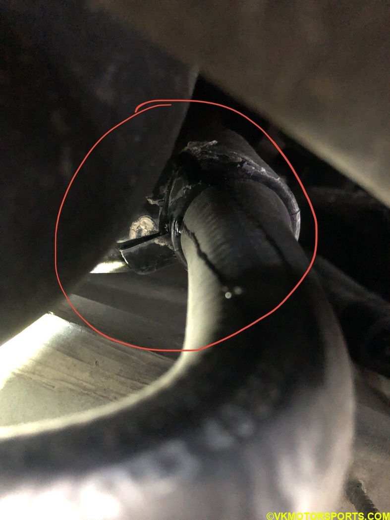 Figure 28a. View from under the car of the cracked hose
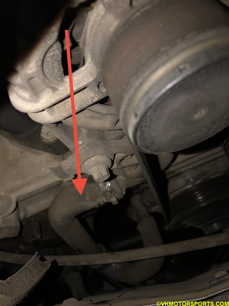 Figure 28b. View from the engine bay of the cracked hose
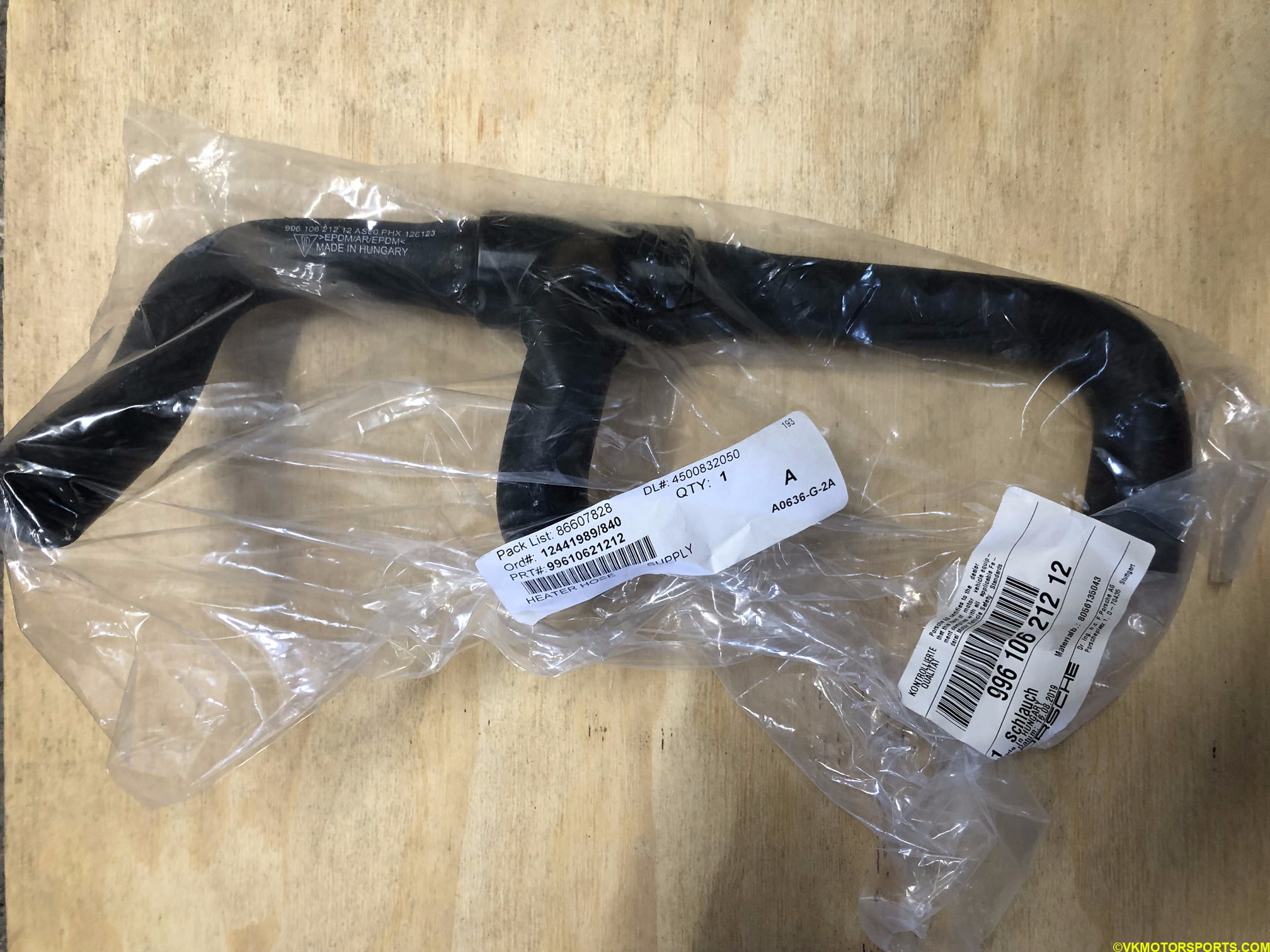 Figure 28c. Hose part# 996-106-212-12
Refill Coolant
Optionally, you could buy a tool like a Coolant Vacuum Refill Kit to refill the coolant correctly in the car. This kit also has a coolant/radiator pressure testing kit in it, so maybe a good combined purchase for the price. Now you need to refill the coolant and bleed it. The recommended way is to just use a vacuum refill pump to push the coolant in. You will need 5.5 gallons of coolant so you need 2.5 gallons of distilled water and 2.5 gallons of the Pink G40 coolant. I mixed 3 gallons of each and then pumped it in. Took a while to get it right, and unfortunately did not take any pictures since it was difficult to hold the pump and then take pictures.
Figure 29 shows the coolant overflow tank filled to the MAX level after this process is done.
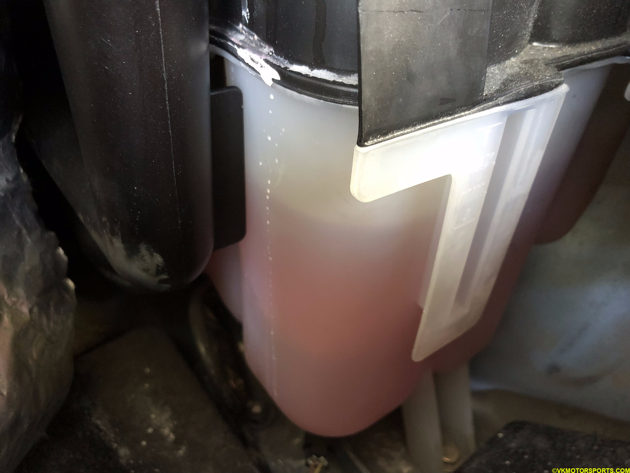 Figure 29. Coolant overflow tank is full
Demonstration
Now start the car and check that the pulleys rotate and there are no leaks. If there are leaks, check the bolts are tightened and you have the hoses tightly on. Below you can see the engine running after replacing the belt and water pump.
Reinstall Covers and Coolant Tank Cap
Once everything is ready and tested, you must reinstall the engine cover (Figures 16a and 16b) and the splash shield (Figure 4) back in place. Then go drive the car and look for leaks again. You may need to drive until the temperature in the gauge shows 180F.
It may also be time to replace your coolant expansion tank cap which is part# 996-106-447-04. I replaced mine since it looked very old.